

(article continued from previous page)
After assembling a robot, you may think your work is complete. But, the difference between a lousy robot and a great robot is that the best robots are modified and tweaked after their initial test runs.
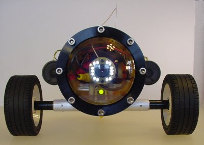
StreamHawk wireless explorer robot coming at you!
The experience of creating a robot can be physically, emotionally, and financially draining. Much like reading a lengthy article, sometimes you just want to be done with it. So, it can be difficult to motivate yourself enough to revise the robot -- particularly if you’re presently disappointed in the performance.
Here are the actual problems encountered in this robot on the first tests:
The first problem needing to be solved was that the microcontroller crashed when receiving commands. I pride myself on writing robust code. And, I write reusable routines and libraries that can be relied on as they’ve been tested in prior robots and electronic projects. I just couldn’t believe that I had a random crash in my software.
I attacked the problem using the following debugging techniques:
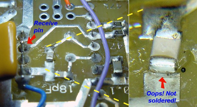
Oscillator crystal SMT capacitor not properly soldered.
Because surface-mount components are so small and aren’t secured by through-hole leads, I prefer to stick SMDs in place with silicone adhesive before soldering. The adhesive is clear and is an electrical insulator. If the adhesive is applied sloppily, then the trace or pad can be partially covered, preventing the electrical component from making contact when soldered.
Although it is difficult to see, a thin layer of clear silicone adhesive is underneath the tiny capacitor that connects to the crystal oscillator that drives the microcontroller. For some reason (stray surface capacitance), the microcontroller is able to run even without this capacitor.
However, when the nearby receive pin is toggled during serial activity, the electrical noise is just enough to bleed into the broken oscillator circuit. Depending on the circumstances, if a character arrives at the wrong moment, the microcontroller clock would suddenly advance an extra step or more at a speed far exceeding the maximum clock rate (20 MHz). Because the transistors won’t all be ready, the states of registers (including the stack pointer and the program counter) will be corrupted.
In other words, the microcontroller is jerked forward even when it isn’t ready with the result of the current instruction. This causes the microcontroller to execute randomly and eventually reset.
Shame on me!
A blob of solder bridges the end of the capacitor to the uncovered portion of the trace to fix the board.
With properly functioning hardware, the rest of the robot can be worked on. The issue of long program commands is addressed in two ways.
First, a set of abbreviated commands are created for the most popular function. For example, FORWARD can also be just plain 'F'.
Second, the previously entered command can be repeated using '='. This makes it easy to position the robot remotely. I can enter “ROTATE LEFT 100” into HyperTerminal, watch the results, and enter '=' to nudge the robot a little more if needed.
The wireless camera came from eBay. It is an inexpensive import without any formal specifications. It is very small. So, it isn’t fair to complain too much about the poor wireless range.
A 20 foot range is fine for head-on views of robot sumo battles. But, it is unacceptable for a robot that is supposed to have wireless adventures throughout my house.
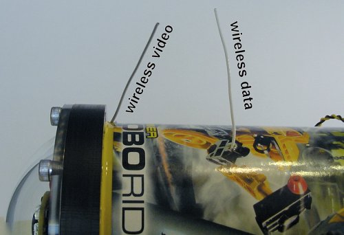
Wireless antennas sticking out a robot’s body.
The first improvement in wireless transmission range is to drill small holes in the robot’s shell to allow the antennas to stand up nearly straight. This also allows the antennas to get away from the other electronics.
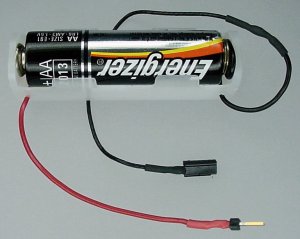
A single AA alkaline battery in a holder.
The second improvement is to boost the voltage provided to the wireless video camera. The camera is designed to connect to a 9 V battery. A fresh 9 V alkaline battery actually provides about 9.6 volts.
The pair of lithium polymer cells that provide power to the rest of the robot produce 8.3 V when freshly charged. Inserting a fresh 1.6 V alkaline cell in-between the li-poly pack and the wireless camera boosts the total camera voltage to 9.9 V. Of course, after a few minutes of usage each cell drops a tenth of volt, providing an optimal and safe 9.6 V for transmissions.
Between the increased battery voltage and the antenna hole, the wireless video range is now around 100 feet indoors (through a wall or two). That’s not fantastic, but it is acceptable for such a small camera.
The final problem to be addressed was that the wheels fell off. No matter how cool and sophisticated you think your robot is, there is nothing more deflating than to have a wheel drop off.
It takes a lot of torque to turn large diameter wheels. This strains the setscrews that attach the wheel hubs to the motor shafts. Additionally, the robot is designed to go over bumps, which can cause screws to loosen.
Each wheel hub contains a single #2-56 setscrew that is tightened with a fairly skinny hex key. My first thought was that the hex key is too narrow to apply enough force to fully tighten the set screw. So, I added a larger #4-40 set screw to the opposite side of the hub. This provides two gripping points per motor shaft and the hex key for the #4-40 is thicker and capable of greater tightening.
But, after a few more trial runs, the wheels still fell off. (Insert swear words here.)
An unusual characteristic of the drive motor on this robot is that it does not have a flat area on its gearbox shafts. It is “splined” instead (lots of grooves parallel to the motor shaft).
I believe the lack of a shaft flat is a contributing factor as the set screw only needs to turn a small amount before contact is lost and the round shaft can freely rotate in the hub. The fastest solution is for me to mill a flat onto the motor shafts.
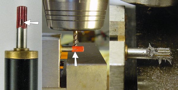
Using a milling machine to mill flats on a steel motor shaft.
If you’re accustomed to machining aluminum, brass, or plastic, then an amusing effect of machining certain steels is that they tend to leaves magnetized particles. (See the far right side of the picture above.)
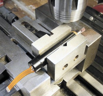
A miniature DC gearmotor held in a v-groove in a vise in a larger vise.
Here’s a look at how the motor is cradled in a small vise. In fact, the small vise (Little Machine Shop #1276) is small enough to fit in a larger vise (Micro-Mark #82577) that is commonly bolted to the milling machine table.
If I were machining many of these motors shafts, then I would prefer to support both ends of the shaft instead of transmitting the machining stresses to the motor’s bearings. Also, something should be done to prevent the shaft from rotating. Fortunately, these motors are solidly built and the gearbox has a high-enough gear ratio that shaft didn’t turn during machining.
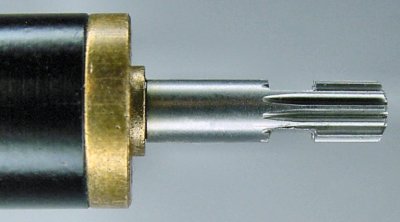
A motor shaft machined to have double flats. Not bad.
Because I was so irritated at having the robot’s wheels fall off despite previous attempted corrections, I decided to machine two flats on the motor’s shaft. That way, both hub screws could prevent the shaft from rotating even if either screw loosened significantly during usage.
So far, the wheels have stayed in place on the altered motor shafts. However, the set screws do eventually loosen after extended usage. Clearly there needs to be a better way to hold onto wheels than just setscrews.
I’m really happy with the total performance of the StreamHawk wireless robot.
The robot now has the capability of driving into the kitchen to annoy my wife from afar -- which is surprisingly easy with the integrated speech module. The robot also has the ability to return to me as a long as my wife doesn’t step on it, pick it up, or turn it over with a dismissive laugh.
There are some additional corrective tweaks that I’d like to make to the robot. Also, it would be nice to make use of the four unused analog pins and the two remaining motor drivers. I think a remote-controlled claw would be a fantastic feature.
I hope you enjoyed reading this article and found some tips or ideas for your own projects.