

The primary purpose of this semi-autonomous robot is to allow the operator to remotely explore rooms in a home.

A robot with a wireless camera, white-LED ring light, wireless data connection, large wheel clearance, and two rear-mounted speakers for the speech module.
The front of the robot has a clear acrylic dome that protects the wireless color video camera and microphone. The dome is available from Electronic Goldmine (#G15338) for $2.50. The camera is an inexpensive import purchased on eBay.
The camera lens is surrounded by an attached surface-mount white-LED ring light made on a custom PCB. The ring light provides lighting for nighttime navigation, close-up shots, and viewing under tables and couches.
An unexpected feature of the ultra-bright ring-light is that it can be used as a passive weapon to force children to back off when they attempt an extreme video close-up.
A pair of salvaged 8-ohm speakers is mounted on the back. The speakers connect to a Devantech SP03 speech module which receives statements over a wireless data connection.
The speech module allows the robot’s operator to interact with people seen on the video feed. However, I’ve noticed that my family members tend to ignore the robot’s demands and/or requests for help. The wireless microphone confirms that the robot spoke, and it also relays the clearly audible human responses that are all-too-often marginally inappropriate.
Two Maxon DC (electric) motors power large rubber wheels so that the robot can pass over doorway thresholds and small scattered objects on the floor. Despite the small size of the motors, they are rated at 3 watt and have 67:1 gearheads. The Maxon motors produce a perfect combination of speed and torque on this 905 gram (2 lb) robot.
The cylindrical body is a Lego Roborider plastic packaging canister. It was chosen for its unique shape and attractive appearance, as well as being lightweight.

This is a three-wheel robot with an unpowered third-wheel on the rear for balance.
The robot’s third wheel is attached to the Lego canister cap. This yellow wheel actually comes from the Roborider set. The wheel was selected because it has low rolling and sliding resistance, due to the wheel being thin and made from plastic.

Photos above and below the robot show the wide stance created by mounting motors end-to-end in an aluminum rod.
The 13 mm diameter Maxon motors fit into a custom aluminum tube, which was machined from a solid rod on a lathe. The rod screws to a plate inside the robot’s main body.
Most robot designs place the motors side-by-side for a compact shape. But, given the uneven terrain of carpets, cables, and toys, a more stable orientation is conferred by placing the robot’s motors end-to-end. Although the extra width increases the chances of getting caught on something, the robot is less likely to roll over.
With the exception of the speakers and motors, all of the electronics are enclosed in the main body case.
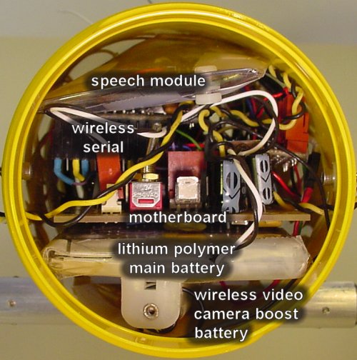
A view inside of the robot crammed with batteries, wiring, and circuit boards (motherboard, speech module, wireless serial card, and so on).
The robot’s main power source is a pair of Kokam Li-Poly (lithium polymer) cells, part# KOK3270. These rechargeable batteries have a 3.27 amp-hour (Ah) capacity at a peak voltage of around 8.3 V.
The nominal voltage of 7.4 V (3.7 V per cell × 2) is adequate for regulating a steady 5 V for the circuit boards. But, the wireless video camera’s range depends on the voltage provided. To increase the wireless range, the voltage to the camera is boosted by an additional 1.5 V from a AA alkaline battery in series with the Li-Poly battery pack (see the bottom of the above picture).
At idle (not moving, lights off, no video), the robot uses about 130 mA. The wireless video camera uses about 100 mA when enabled. The variable-brightness ring light can use up to 120 mA. Movement uses between 200 mA to 400 mA.
Therefore, maximum sustained current consumption is approximately 750 mA. At that rate, the batteries will theoretically last 4 hours. (In practice, the robot is not constantly moving and the ring light is usually off, which is saves a lot of power. But, it isn’t a good idea to completely discharge the battery and the video camera will perform poorly as the voltage drops.)
The wireless video camera receiver and wireless data transceiver are connected to a standard PC. The wireless data modules are Digi (formerly MaxStream) 9XCite 900 MHz 38400 baud.

ImageCraft compiler, HyperTerminal, and ATI Catalyst Media Center on a personal computer to develop, control, and see the view of the explorer robot.
An ATI video card with Catalyst Media Center displays the video feed on a floating window. Data is sent and received using plain old HyperTerminal. An embedded program written in C on the ImageCraft AVR compiler allows the Atmel AVR ATmega644 microcontroller to interpret text commands issued in HyperTerminal.
Single immediate commands can be issued remotely. Or, an interpreted program can be remotely written, modified, saved, and loaded from the robot’s microcontroller EEPROM. Here’s an example:
			StreamHawk ][+

			Revised: February 10, 2008

			Power supply: 8.0 V


			]load

			1 FORWARD 10000

			2 ROTATE RIGHT 730

			3 FORWARD 11000

			4 ROTATE LEFT 650

			5 FORWARD 6000

			6 SAY “Visit Robot Room dot com”

			7 WAIT 400

			8 ROTATE RIGHT 1500

			9 FORWARD 6000

			10 ROTATE RIGHT 650

			11 FORWARD 10000

			12 ROTATE LEFT 600

			13 FORWARD 10000

			14 SAY “All done!”


			]camera on

			]run
(The amounts specified are in arbitrary encoder counts based on the Maxon encoders. At some point I'll change the embedded interpreter code to actual distances and angles.)
The above instructions cause the robot to follow a route from my office, through the hall, to the living room. The robot pauses to speak before heading back to the office. Because the robot uses dead reckoning (instead of external sensors), it doesn’t always go exactly as planned.
Here is the wireless video from the robot’s point of view:
And here is the video from an external view of the robot on that same run:
Let’s take a look at the motherboard and other PCB modules used in this robot...