

I know that you’re in the middle of reading an article about rocket launching systems. But, while we’re examining tiny details of an etched rocket igniter circuit board, I wanted to quickly mention a method of magnifying subjects for photographs.
Normally, when you are taking a close-up picture, you select the macro mode on your camera. If you’re fortunate enough to have a camera with an interchangeable lens, you can switch to a macro lens. If that’s not enough, spacers are available to increase the distance between the lens and the imaging sensor.

Panasonic DHC GH1 with extension tubes and macro lens
The spacers don’t contain a lens; they’re just empty air -- thus the fancy name 'extension tube'. The higher quality extension tubes include pins to connect the lens circuitry to the camera body. The less expensive versions require you to focus manually.
I chose a pair of extension tubes for micro 4/3s cameras: the Fotasy DG auto-focus macro extension tubes. One is 10 mm and the other is 16 mm. You can combine them to get 26 mm -- which is what I used in this case.

Fotasy DG extension tube for micro four thirds camera
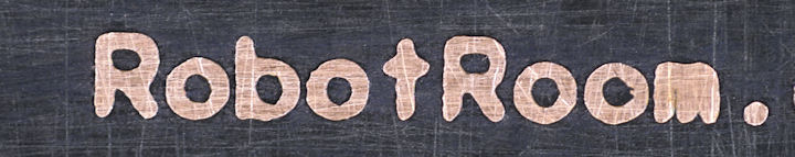
Extension tubes can significantly increase zoom. For example, the etched letter 'R' of Robot Room is nearly twice as big.

Enlargement difference with extension tubes
The words no longer fit in the photo.
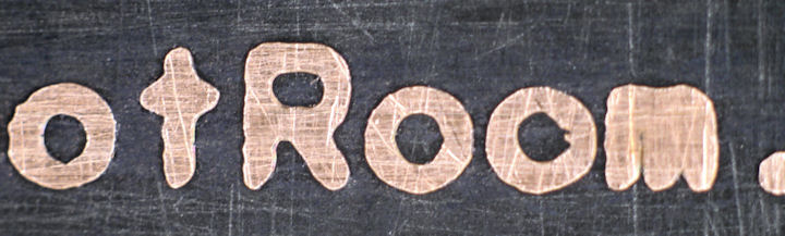
Maximum enlargement: standard macro lens (top), with extension tubes (bottom)
Unfortunately, image quality is poorer at this size. Even with a tripod and shutter remote, it seems I’m getting significant blurring from the tiniest vibrations in the house. I’ll need to experiment with other setups.
The above photograph shows that the letter 'm' did not etch particularly well. To determine the cause, I looked at each stage.
The printout is crisp. With my previous layout software, I had to take a screenshot and paste it into a paint program to flip it over. But, newer software supports mirrored printing natively. That means I’m no longer getting pixelization.

Smooth print out
The ironed transfer film was a major source of problems -- look at the letter 'm' in the photograph below. Not only did I use too much heat, but I lifted the film and then reapplied heat to try to fix some problem areas.

Poor transfer due to overly high temperature
The etching itself seems great (based on recreating the image on the transfer film). For example, the lack of well defined inner corners on the letter ’t' seems like an etching problem, except that it clearly matches the shape of the ’t' on the transfer film. Even the notch in the final 'o' of 'com' is faithfully reproduced. So, the etching process does not seem to be at fault here.

Excellent etching
I suppose I can conclude that the PCB etching process was ruined by too much heat and reapplying the transfer film after peeling it back for inspection. Although the rocket igniter circuit still works fine, it doesn’t look great.
Now that the PCB is ready, we can connect switches to it.