

Lego makes high-quality wheels in various shapes, styles, and sizes that are perfect for small robots. But, Lego only makes a couple of electric motors, with limited voltage, gearing (speed / torque), and sizes.
You can purchase lots of different kinds of new miniature gearhead motors from Solarbotics or the RobotCombat store. Or, you can buy used or surplus Maxon, Faulhaber, and Portescap gearmotors from eBay or online electronic resellers.

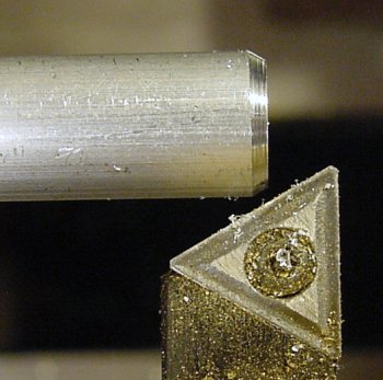
A Solarbotics gearhead motor connects through a machined metal coupler to a Lego wheel.
It would be great to combine the variety of Lego wheels with the variety of gearhead motors on the market. By making a coupler, you can adapt a standard motor shaft to a Lego cross axle to attach LEGO wheels. (Another example appears on the Machining page.)
Since the coupler has a standard LEGO cross axle, no alteration of the wheels is required. Different wheels (and even gears) can be used by simply pulling them off and pushing them on.
In my first book, Robot Building for Beginners, there are instructions for making such a coupler using telescoping tubing and epoxy. In my second book, Intermediate Robot Building, the same coupler can be made on a milling machine.
This article presents the steps to machine an aluminum or brass coupler using a lathe. A lathe is probably the best machine tool to create cylindrical objects. These instructions may be useful to you to learn about the fundamental operations on a lathe, even if you don’t want to make a motor-to-wheel coupler.
As an example motor, I have selected the GM7 from Solarbotics (costs $7). But, the coupler can be made to fit almost any small motor.
The GM7 has an 8.5 mm long motor shaft that is approximately 2.17 mm in diameter. Because the shaft is splined (it has ridges), it is somewhat difficult to measure the exact diameter.
If you choose a different motor, you'll need to choose a drill diameter that matches your motor’s shaft diameter. Also, you'll need to vary the length of your coupler, to accommodate the length of your motor’s shaft.
The coupler can be made from almost any rigid material. For example, couplers can be made of PVC, Delrin/acetal, nylon, or polycarbonate plastic. On the other end of the spectrum, couplers can be made of steel or stainless steel.
For beginners, the best choice of material is brass (360 alloy) because it is the easiest to machine. However, the example photographs show aluminum. Aluminum is inexpensive and lightweight, but is more difficult to machine because it tends to be clog up drills.
The coupler is made from 5/16 inch diameter rod stock. 3/8 inch diameter rod stock is also acceptable, but 1/2 inch diameter is unnecessary for a metal coupler that attaches to a skinny plastic LEGO axle.
Except for expensive or exotic materials, rod stock is most often sold in long lengths. For example, McMaster-Carr sells 5/16-inch diameter 360 alloy brass for $17 (#8953K47) for 6 feet. As delivered, this is too long to work with in a miniature lathe.

Cutting down long rod stock with a hacksaw.
Place the long rod into a vise. Use a hacksaw with a fine-tooth blade to cut off roughly one foot of material. (Cut off several feet if you’re going to be making many couplers.)
The hacksaw leaves a jagged and crudely angled end that needs to be cleaned up. But, that’s fine. A hacksaw is a tool for rough cutting, whereas a lathe is a tool for precision machining.
It would be wrong to use a precision tool for cutting down large stock. And, it would be wrong to expect a rough cutting tool to leave a precise edge. So, don’t worry if your hacksaw cutting job looks horrible.

Smoothing the rough end of a metal rod by facing it in a lathe.
Most lathes have hollow shafts to let you insert excess rod through the spindle chuck (the part that grips the rod). That is, you only need to expose a short length of the rod for the machining operation. We want it to be as short as possible, as the unsupported section of rod flexes during machining.
Notice on the left side of the above photograph that the amount of rod beyond the jaws of the chuck is enough for one coupler.
On the cutting tool, only the very tip is going to remove material. The other portions of the cutting edges need to stay out of the way. The cutting edge would quickly dull if the entire side were rubbing against the face of the rod with each stroke. Only a slight angle is needed to make sure only the tip makes contact (greater angles are also acceptable).
With the lathe spinning, the cutting tool is moved from the front edge of the rod to the center of the diameter of the rod and then back to the front of the rod (until the cutting tool is no longer making contact). This removes just a little bit of the rough edge.
Then, the cutting tool is moved slightly to the left by a small amount. Then, the cutting tool is moved front-to-center-to-front again to remove a little more material. This is a slow, steady process.
Don’t plow the cutting tool into a solid rod and expect it to produce a clean square end. You'll end up breaking the tool and bending the rod. Precision machining is a series of small cuts.
The end of the rod is slowly shaved to a nice clean, square end. This operation on a lathe is called “facing”.
Small chamfer cut on a lathe with an angled cutting tool.
If desired, a chamfer (angled edge) can be cut with a cutting tool at a different angle. This removes the sharp edges that might otherwise cut your fingers.
Now it is time to drill holes for the cross axle and the motor shaft...