Attention Readers: To access the book's secret resource page on this website,
be sure to type the web page address from page xxii in the same upper/lower case as printed in the book.
- Packed with over 300 photographs!
- Dozens of schematics with part numbers and sources
- Written by the host of RobotRoom.com
Includes all of the step-by-step instructions you need to create your own robot that can explore rooms,
follow lines, or battle opponents in mini sumo.
The circuits and parts in this book are presented as independent modules,
so that you can build the complete robot as described or apply the modules to your own unique robot designs.
- Detect obstacles, walls, and opponents with an infrared sensor
- Find out how to fine-tune the emitters as well as detect leaks
- Make a simple power supply and then beef it up to be robot-worthy
- Select drills and taps and apply machining techniques to make your own wheels or circular robot platforms

Contains complete schematics for Roundabout, a room explorer that requires no programming and uses
only off-the-shelf electronics.
For readers with a software background, upgrade Roundabout with a microcontroller of your choice
to prevent the robot from getting trapped in places that would confuse the mindless adventurer.
Complete descriptions of common microcontroller features and recommended selection criteria are included.
Find out how to make a motor (and robot) go forward, reverse, coast, and brake.
Begin with the most rudimentary motor driver and build up to the classic full-motion control H-bridge.
Significantly improve motor power and driver efficiency by using MOSFETs.
Or, simplify your robot designs with prepackaged motor driver chips.
- What's the value of a robot heartbeat?
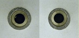
- What's the purpose of the wavy lines in photocells?
- What's a good use for aluminum angle stock?
- What electronic part should you sand?
- How do you avoid exploding a capacitor?
- Teflon slides are wonderful, but what art supply performs better on the front of the robot?
- Can a well-placed single switch avoid obstacles better than a pair of feelers?
For readers of Robot Building For Beginners, this book is the perfect next step in the learning process.
If you already have basic robot building experience, it is not necessary to have read the first book
to enjoy this book.
Click here to order your copy, today!
Chapter 1: Assembling a Modular Robot
The first chapter lays the groundwork for the modular philosophy throughout the book.
A brief introduction to a miniature milling machine is provided to encourage robot builders to
consider the merits of such a device (although a milling machine certainly isn't required for this book).
Chapter 2: Homemade Motor Couplers and Errors to Avoid
Attaching a motor to a wheel can be more difficult than you might think.
This chapter presents an alternate technique (step-by-step instructions follow in Chapters 3 and 4)
from the telescoping-tubing technique presented in the first book.

This chapter contains photographs of clear (acrylic) couplers to show off the inner details.
This is especially useful on couplers that have common mistakes.
Following each problematic coupler is a photograph of how an attached wheel would then rotate.
Chapter 3: Making a Fixture and Drilling Solid Rods
One of the most frustrating machining problems is trying to drill a hole exactly in the center
of a round piece, such as a rod.
This chapter describes one technique that provides excellent results.
This chapter includes a checklist for selecting a drill for machining aluminum or plastic.
An explanation is provided for why you should create a fixture and the benefits of an X-Y table (found on milling machines
but can be added to a drill press).
Chapter 4: Tapping Holes and Selecting Setscrews
This chapter describes three differed tap styles for making threads in holes
(so that a machine screw can be inserted).
In particular, this chapter explains why you might choose one tap style over another.
The solid-rod coupler project started in Chapter 2 is finished here.

Chapter 5: A Motor Inside of a Wheel
Many of the best sumo robots have wide wheels with motors installed inside of them.
This places the largest mass (the motors) directly on the wheels for increased traction.
The other advantage to this placement is that the mass is
low to the ground to make it difficult for an opponent to tip the robot over.
This chapter describes one method for building motors into wheel hubs, while still
permitting them to be easily removed for servicing.

This chapter has a lot of interesting machining tips (mating parts, when to use an unthreaded hole, Silver & Deming drills).
In fact, this chapter shows how to make your own wheels, if you so desire.
Chapter 6: Standards for Electronic Experiments
This is a transitional chapter which tells you how to read the schematics in the book,
provides suggestions on bench power supplies, and debates the inevitable changeover to surface-mount technology.
(By the way, all of modules in this book are based on through-hole parts, which are easier
for the hobbyist to use.)
Chapter 7: Linear Voltage-Regulated Power Supply
Nearly every robot needs a regulated supply of power.
This chapter begins with a really simple +5V power supply circuit based on the classic 7805.
The circuit is improved with reverse-battery protection via a diode, followed by a more
voltage-efficient solution that also only requires one component.
A few pin-compatible low-dropout versions of the 7805 are swapped into the power supply circuit
and the performance is then compared.

Chapter 8: Robot Power Supply Improvements
Unlike some other electronic devices, robots can place extra strain on their power supplies.
This chapter beefs up the power-supply circuit presented in Chapter 7, by adding
bulk capacitors, regulated voltage protection (zener diode),
overcurrent protection (resettable fuse or PPTC),
rapid turn off (capacitor discharging through a high-wattage resistor),
and noise reduction (short leads and voodoo capacitors).
You may choose to implement none, some, or all of these techniques on your next robot.
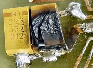
This chapter looks at capacitors in great detail (Chapter 11 also includes some tips).
In particular, proper working voltage (WV), placement, and sizing are discussed
to provide the longest practical lifespan.
Chapter 9: Motor Drivers - Bipolar
This chapter begins by demonstrating the four modes (clockwise, counterclockwise, coast, and brake)
available in a standard DC motor.
Motor driver circuits are built step-by-step from the most simple (single transistor) all
the way up to the classic H-bridge.

Have A Nice Day, a mini-sumo robot, lowers its scoop with a motor controlled by only a single transistor.
This chapter mainly focuses on bipolar transistors, such as the 2222 and 2907.
The benefits of the popular 4424 and 4427 interface chips
are described when the chapter branches into interfacing the motor drivers
to logic chips and microcontrollers.
This is a massive chapter.
It was personally one of the most satisfying to write.
Chapter 10: Power MOSFET Motor Drivers
If the last chapter was massive, this is... (what's bigger than massive? colossal?)
This is the kind of chapter that you can choke an editor with.
The MOSFET Motor Driver chapter begins by recreating the bipolar motor driver circuits from Chapter 9,
but with power MOSFETs instead.
This was a good opportunity to talk about pull-up and pull-down resistors,
shoot through, and body diodes versus discrete Schottky diodes.
This chapter includes the key criteria for selecting a MOSFET.
A lot of attention is focused on resistance, including paralleling MOSFETs for improved performance.
(Steady-state Parallel MOSFETs self-balance due to their thermal coefficient,
as opposed to bipolar transistors that can experience thermal runaway. Find out what that means in this chapter.)
The chapter concludes by describing some popular motor driver chips, which are more
compact and feature rich than motor drivers you can build by hand.
The motor drivers are then compared in head-to-head performance testing
for powering miniature DC motors.

How good is the MC33887 compared to a discrete 2222/2907 H-bridge, 4427, or discrete HEXFET H-bridge?
What's the deal with the SN754410?
Chapter 11: Infrared Detector
The Panasonic PNA4602M 38 kHz infrared detector is very popular in the robotics community, especially in sumo robots.
The responsiveness of the detector is analyzed along with a simple method of testing it (and any other 38 kHz detector, like those made by Sharp).
(The PNA4602 has been replaced by the nearly identical Vishay TSOP4038.)

This chapter steps you through making a complete dual emitter, detector,
and bicolor indicator circuit based around a common logic chip.
You can use this stand-alone detector on your robot for detecting walls, obstacles, or even opponents.
Selection criteria for infrared emitters / infrared LEDs are listed, along
with selection criteria for timing and noise-reduction capacitors.
Chapter 12: Fine Tuning the Reflector Detector
This chapter finishes up the infrared reflector detection circuit.
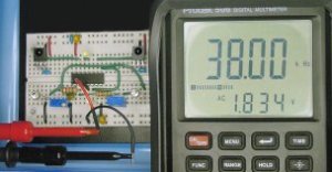
The chapter begins with several techniques for tuning the 38 kilohertz square wave:
by hand, using a multimeter with a frequency mode, and with an oscilloscope.
Four alternatives are provided for avoiding side leakage in infrared emitters.
Limitations of infrared detection are revealed, including the effects
of shapes, ambient lighting, and materials.
Chapter 13: Roundabout Robot
It turns out that the electronic modules and machining techniques presented thus far in the book
can be connected together to make Roundabout, a room-exploring robot.
Detailed photographs of Roundabout are shown from all angles.
The circuitry and motions are described.

The particulars of machining Roundabout's robot body are described in the second half of this chapter,
including tips on using templates, machining multiple pieces at the same time,
and two methods of targeting a drill.
A compact method of mounting motors side by side is shown, along with choices
on gearing up, gearing down, and idle power train transfer.
This chapter also provides a couple of suggestions for making slides for the robot,
and when not to make the robot slide.
During the building of Roundabout, a couple of mistakes are caught and described in this chapter.

Chapter 14: Test Driving Roundabout
Before launching the robot, a series of tests are performed that are applicable to any robot.
These tests include a safe way to drain power and a simple way to measure current usage.

The robot is then put through the paces.
A low-tech approach to test-facility materials reveals the robot is socially aware (okay, maybe not).
Actually, a significant limitation to having a brainless robot is discussed, along
with why a round robot body may not be the best shape.
Chapter 15: Microcontrollers

This book does not focus on one brand of microcontroller over another.
Although a particular microcontroller, the 68HC908KX8, had to be selected for the upgrade of Roundabout,
this chapter describes the various features available in 8-bit microcontrollers
in a generic way.
Selection criteria and a few recommendations are made, but the examples in the book
are generalized for use with any microcontroller you prefer.
This chapter explains the benefits of a microcontroller over an off-the-shelf logic chip
(including a potential improvement to implementing an infrared reflector detector).
It then describes the steps that you might go about to program a microcontroller and test it,
including a simple heartbeat indicator.
Chapter 16: Upgrading Roundabout with a Daughterboard
This chapter returns to working on Roundabout. In this case, upgrading the robot by adding
a microcontroller and other features.
Ordinary 0.1″ spaced boardmount sockets permit the daughterboard to be snapped
right on top of the motherboard.
This technique is applicable to any modular robot.

Also included in this chapter are tips on selecting machine screws,
trimming and reheating solder joints,
screening out ambient lighting,
debouncing inputs with both hardware and software,
and adding DIP switches.
Chapter 17: Floor Sensor Module
Besides deep-diving in motor drivers and voltage regulators, I always wanted
to fully understand the performance of CdS (cadmium-sulfide) photocells / photoresistors.
This chapter explains the purpose of the wavy lines and gap size, and why you can't
tell the resistance by its cover.
Schematics and breadboard examples show the common ways of connecting photoresistors in circuit.

The middle portion of the first section of this chapter should hopefully dispel the myth that photoresistors
provide “near linear” responsiveness.
The actual mathematical formulas and how they relate to a particular photoresistor's sensitivity are explained.
Two major weaknesses of photoresistors are divulged: large manufacturing variance and very slow responsiveness.
After reading this chapter, you'll avoid CdS photocells in your next line-following robot champion.
There is a wonderful alternative to CdS photoresistors, the light-to-voltage converter IC.
It's easy to hook up and is available to sense white light or various colors (red, green, or blue).
This part is employed in making a floor sensor board that connects to Roundabout.
The shades and baffles on the board are lightweight, fairly simple to make, and definitely improve performance.

The chapter ends with algorithms for implementing line-following and robot sumo on either
Roundabout or any other robot with similar modules.
Full KX8 assembly source code for Roundabout is available online.
Chapter 18: Robot Stew
The last chapter is where all the leftovers go.
Yet, the wide variety of subjects make this one of the most interesting and easy-to-read chapters.
The chapter begins with an LM386 audio amplifier circuit and its implementation.
It is used along with a PWM (pulse-width modulator) pin on the microcontroller to play
music as the robot drives around.
Besides being fun, musical tones are a good debugging tool, especially for a robot that lacks a text display.
A method for transcribing and programming music is included.
The next portion of this chapter describes a roomy upgrade to Roundabout's body.
It includes Teflon roller slides, integrated wheel slots, and colorful homemade spacers.
But, best of all, are the instructions for making quick, dependable, accurate motor mounts.
Two other motor mounts and another type of motor-to-LEGO coupler are detailed.
Then it's on to comparing four types of sensors on a solar robot.
Which do you think worked best: photoresistor eyes, metal-whisker obstacle detectors,
a front-contact bumper switch, or an undercarriage contact switch?

Last, but not least, Roundabout goes video!
Here's a simple way to add telepresence to your robot.
The book was a joy to write. I hope the content will appeal to readers of my first book as well as to experienced robot builders.
Click here to order your copy, today!
|


