

(article continued from previous page)
The Flip-Flop Robot has a pair of switches on the front and back of the robot that connect to wooden rods. When the robot runs into an obstacle or wall, the bumper rod pushes the switches. This allows the robot to detect a barrier and change direction, as though a user had pressed an ordinary “change direction” button with their finger.
The switches are “snap action” style. The lever arm on the switch means that very little force is required to activate. Furthermore, the lever arm can move a greater distance that most switches, without damage.
Unfortunately, the curved body of the container and the relatively small switches makes it difficult to mount them while still allowing enough room for the wooden rod to be fully depressed. Some mounting brackets are needed, but I promised myself this robot could be made without fancy machining equipment.
Let me think. What material is rigid, commonly available to hobbyists, but easily drilled and trimmed? Circuit board!
Unetched, single-sided or double-sided copper circuit board can be purchased from most electronics retailers (Digi-Key, Mouser, Jameco, etc). In this case, I’m using some leftover scrap of a 1/16-inch thick board. Alternatively, you can use etched circuit boards that you salvage from recycled equipment or from failed projects.

Copper-clad board and paper template taped to wood.
The copper board is taped to a piece of wood to keep it from bending during fabrication. Believe me, this is a lot easier than trying to drill holes with a bare board in a vise or hanging off the end of a workbench.
To obtain reasonable accuracy, I made up a bracket template in a drawing program on my computer. But, you can simply measure and mark holes by hand, if you prefer.
Each bracket needs four holes:
Four brackets are needed
The fiberglass sheet that is laminated in the center of a circuit board produces irritating dust when drilled and cut. Wear proper protection such as a dust mask and goggles.

Nail pricks help center the drill.
The drill tends to wander on slick material. Pre-punching a small mark with a nail can make a significant difference in getting the drill to dig in where you want it.
Admittedly, my marks are pathetically off-center in the above photograph. Fortunately, there is enough wiggle room in the screw holes that this doesn’t make any difference.

Cutting copper clad switch brackets free with a Dremel cut-off disc.
After drilling all of the holes for each bracket, separate the brackets by cutting across the lines with a cut-off disc. Make sure the tape is secure enough to prevent a bracket from flying across the room during separation. You are wearing a breathing mask and eye protection, right?
Hand machining is not very precise. Furthermore, the curved corners of the candy container add complexity. If the switches aren’t symmetrically placed on the robot’s body, then the bumpers are going to be crooked and the functionality may be compromised.
How can each bracket be consistently positioned to mark the locations for mounting holes?
Lego building blocks to the rescue again!

A fixture made of Lego bricks helps position the switch consistently before marking holes for bumper brackets.
A large base plate has a pair of beams that form a corner. An extra flat piece (yellow in the far left of the photograph) is installed on the front beam to make sure the snap-action lever switch sticks out far enough.
After screwing a switch to a plate and lightly attaching a piece of masking tape, the corner of the switch is aligned by eye to the corner of the Lego fixture (see the green arrow in the above photo). Then, the blue tape is pressed against the side of the container. The tape frees up my hand to mark the hole locations with a felt-tipped marker.
Drill two holes in each corner as marked on the candy container.
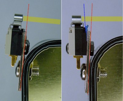
Correcting switch angle with masking tape shim.
Oh noes!
The curvy corners are affecting the angle of the switches! This would make it impossible to connect a straight rod between a pair of switches.
I briefly considered correcting the angle by bending the metal lever arms on the switches. But, they’d most likely break off.
A gentler solution is to shim the switch in the opposite direction to balance the angle. A shim is a very thin piece of material.
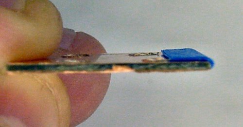
Multiple masking tape layers shim the end of a bracket.
To shim the switch angle, build up a couple of layers of masking tape (mine took three strips) on the tip of the bracket. The tape should be placed only partially down the bracket so that only half of the switch is resting on the tape. If the entire switch rested on the tape, then the switch angle would be unaffected.
I suppose the tape is a bit of a hack. However, you’d be amazed how often a homemade robot needs a little bit of tweaking here and there to perform optimally.
There are just a couple of steps remaining before we can concentrate on the electronics.