

Sweet was one of my first line-following robots, and it remains popular even today. Many years later, I reprise the concept by building a robot inside of an m&m’s candy tin shaped like a VW Bug (Volkswagen Beetle).

Yummy (left) and Sweet! (right) are robots based on candy tins
Yummy was supposed to be a weekend project; quickly assembled from existing boards and pieces that were lying around. Instead, the robot took several months to make. Part of the reason that it took so long is that I chose to reuse existing boards rather than thinking the design through completely and designing a suitable PCB from the start. Reusing a board from another robot meant extra point-to-point wiring and trying to connect sensors in unusual ways.
The other reason why Yummy took so long to build is that I spent a lot of time machining motor mounts and wheel hubs to fit the narrow width of the candy tin. Compounding the difficulty, rather than using Lego tires, it was important to me to retain the existing wheels.
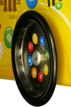

Left: Narrow slippery wheels on candy tin. Right: Rubber band tire to provide grip
Fortunately, a snug-fitting pair of pastel blue rubber bands were found in an assortment pack and attached with glue to the steel wheels. This provides traction such that the motors won’t simply spin the wheels in place. Rubber bands aren’t a perfect long-term solution, as eventually the rubber will degrade and crumble.
Inside the robot are the standard components you’d expect.

Cross section of Yummy robot
I have enough experience with line-following robots to program a smooth algorithm. However, it seems like the m&m’s characters would be pretty poor drivers, so I kept the first draft code which results in heavy fishtailing.
The next pages go into greater details about how the robot was made, and what problems were encountered along the way.