

The Yummy robot is based on an automobile candy tin. Therefore, it seems only fitting that it should have working headlights and taillights. (A movie of the robot driving can be seen on the previous page.)

Yummy line-following robot
The diameter of the lights printed on the car body just about match a 10 mm LED. That size of LED is double the diameter of a standard T 1 3/4 LED.

Red and white 5mm and 10mm LEDs
The headlights are white water-clear 30 degree (VAOL-10GWY4). The taillights are red diffused 60 degree (SSL-LX100133SID). They were obtained from Mouser Electronics.
Holes for the LEDs were ground out using a Dremel rotary tool. I’d occasionally stop grinding to try to fit the LED in the hole. That gave me a visual indication of how much still needed to be cut away. The holes are a little imprecise, but look acceptable after the lights are installed.

Hole ground out for taillight
It is difficult to attach things to sheet metal, particularly if it is coated with a non-stick surface for the purpose of containing food. Super glue doesn’t work, because it doesn’t fill gaps. Although epoxy is a little messy and takes time to cure, it is a better choice than super glue. With a little scraping and patience, clear epoxy secures the headlight LEDs in place.

White LED epoxied into crudely cut hole
For the tail lights, I wanted a Fresnel lens that matches the look of real cars. Chicago Miniature manufacturers a series of lenses that are perfect.
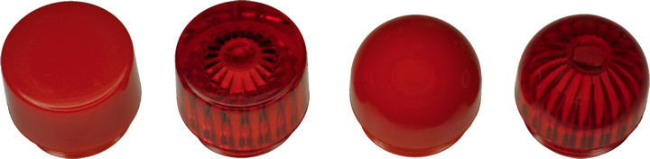
Chicago Miniature red LED lenses
Pictured above, left to right:
For standard 5 mm LEDs, there are also white lenses (CMC313CTP) and red lenses (diffused CMC313RTP, Frensel CMC321RTP). They would be a good choice for a semiflat indicator on a project case. However, they don’t appear to alter the LED focus enough to recommend for diffusion purposes.
The 25P-326R red domed lens selected for Yummy has a threaded base. Presumably, this allows the lens to be unscrewed to service the bulb or to replace a damaged lens. It would have been incredibly difficult to machine a matching threaded socket to attach to the stamped metal tin. A matching nut might have been okay, except the tin is not flat at that location. So, for this robot, I epoxied the lens into the hole.
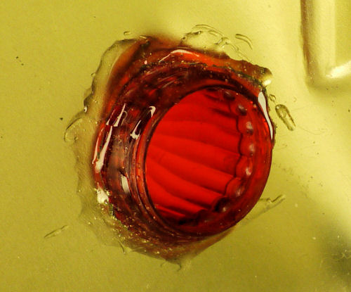
Epoxy secures taillight LED lens
The LED circuit is very simple; similar to the blue and white LEDs on my jack-o-lantern. The headlights consist of two white LEDs with a current-limiting resistor. The taillights consist of two red LEDs with a current-limiting resistor. For battery efficiency, each set of LEDs are in series, not parallel.
We need to calculate the value of the resistor when the LEDs are illuminated at the desired brightness. Although these LEDs are rated at 30 mA, I chose to run them at a more-standard 20 mA to save battery power.
The voltage drop of the pair of white LEDs using my LED test tool at 20 mA was measured as 5.64 volts. Because 5.64 V is higher than the 5 V regulated power supply on the PCB, the white LEDs need to be connected to the 8.4 V lithium polymer power source.
			voltage to drop = 8.4 V battery - 5.64 V used by white LEDs

			voltage to drop = 2.76 V
			current-limiting resistor in ohms = 2.76 V / 0.02 A maximum current  [same as 20 mA]

			current-limiting resistor in ohms = 138
138 ohms is not a standard resistor value. Instead, I selected 120 ohms, which will result in 23 mA of current. Normally, I’d make the value more resistant to ensure the LEDs won’t overheat. However, since these LEDs are rated at 30 mA, driving them at 23 mA isn’t an issue. Also, 8.4 V is the peak voltage for the battery pack, which will drop rapidly to the 7.4 V range, resulting in even lower current.
I performed the same tests and calculations for the red LEDs, and ended up with a 47 ohm resistor for them. This resistance is lower because the red LEDs are supplied power from a 5 V regulated power source, rather than the higher battery voltage.
Recall that the main PCB was designed for another robot and is being reused in this project. Therefore, I needed to create a component carrier sub-board with connections for the LEDs.

Headlight and taillight component adapter board
This is made from single-sided perfboard because the circuit is so simple. It isn’t worth etching a PCB.
One of the irritations of using perfboard is cutting it to the correct size. I usually use a Dremel or hacksaw, which leaves the edges a bit askew. So, I created a fixture from a flat bar of aluminum by milling a short recess on one end.
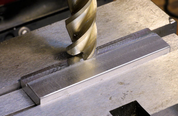
Milling a recessed flat
This holds up the small piece of perfboard high enough in the vise, while bracing it in a sandwich between the back and the front jaws. The edges can be quickly machined square.

Milling PCB edge square
Square edges aren’t just for mollifying OCD, the straight sides make it possible for the PCB to be held flat securely when drilling holes.

PCB with squared edges is easier to drill
Although a small portion of the threaded end of the tail light lens sticks out from the thin sheet-metal body, the final result is quite appealing.

Tail-light view of Yummy, a line-following robot
Next, let’s take a look at the main printed circuit board that controls the robot.