 |
David Cook ROBOT ROOM™ |

|
| home | projects | contact | copyright & disclaimer | books | links | ||
|
Roundabout Printed Circuit Boards Assembly Tips
|
 Roundabout's three printed circuit boards: motherboard (top left), daughterboard (top right), and floorboard (bottom middle) AVAILABLE AT SOLARBOTICS! Parts #RNDMPCB, #RNDDPCB, and #RNDFPCB. Or part #RND Deal for the bundle. Printed Circuit Boards This page contains component placement instructions for the printed circuit boards (PCBs) for Roundabout, the room-exploring, line-following, sumo-battling robot. This information is applicable for boards matching my template, whether you purchased ready-made boards or etched your own. In any case, you need the book Intermediate Robot Building to understand the circuits and to obtain the online resources. The link to the online resources page is on the final paragraph of page xxii. The online resources page contains updates, templates, PCB files, source code, and the parts list. Download the parts list spreadsheet to see part descriptions, part values, which board it is located on, part prices, and example suppliers. Because of limited free space on the PCB itself, some parts are only labeled with their part number ("C2") without their part value. Simply look up the part number in the spreadsheet for all the information.  Left: Roundabout PCB #4 screw hole pattern matches Sandwich PCB. Right: The daughterboard also includes smaller holes for tapping, if desired. Screw Holes There are four large screw holes on the boards (on the floorboard, only the rear two holes are necessary). These are for attaching the finished boards to the robot's body with #4 screws. On ready-made boards, the screw holes are not threaded -- the screws should simply pass through. If you're etching your own board, you can choose to drill a smaller hole and tap it, if you desire. The motherboard, daughterboard, and rear two screw holes on the floorboard match the same pattern as those on the Sandwich PCB. This makes it easy to install the Roundabout circuitry inside of or on top of Sandwich's body if desired. The daughterboard features five spare screw holes (two in the rear of each side and one in the center) that are small enough to permit the holes to be tapped with threads for #4-40 screws. PCB laminate isn't the best material for tapping, so consider these holes for light-duty use, such as mounting a thin speaker or decoration. For heavier usage, use a washer and a nut instead of relying on threads made in the PCB. 
 Left: half circle marks a via. Right: Bare wire soldered on both sides of the board to complete a via Vias Throughout the board are a number of holes with a half circle above them. These indicate locations where the front side of the board needs to be electrically connected to the back side of the board. If you're etching your own board, you'll need to insert a bare wire (no plastic insulation) into the hole and solder the wire on both the front and back sides. If you've got a ready-made board, ignore the half-circle holes; the board manufacturer has plated through the holes, making the connection and saving you time. Alternatively, you can use the half-circle holes as test points.  Left: PCB test points consist of a single hole with a square silkscreened around it. Right: Insert a 1-pin header to test a voltage (or frequency) at that point. Test Points There are “official” test points throughout the boards. The test points are usually labeled with “TP” such as “+5VTP” or “TP38kHz”. On the ready-made boards, the test points are usually surrounded by a single silkscreened square. You can attach a piece of wire (pointing out straight or in a loop) or a 1-pin standalone header to each hole to allow hook clips to attach for testing. Or, you can leave the test point holes alone and ignore them. They are not necessary for the robot to function. On the motherboard, I would recommend at least using the TP38kHz and GND test points to make it easy to connect a multimeter in frequency mode to tune the emitters.  Resistors Resistors are non-polarized parts, and thus can be inserted with either pin in either hole.  Left: Aluminum electrolytic capacitors have a stripe to indicate the negative (or GND) lead. Right: Tantalum capacitors have a stripe or '+' to indicate the positive lead. Capacitors Larger value capacitors (1 µF and up) are usually polarized parts. That means you have to insert the correct lead into the correct hole or else the capacitor will be damaged when power is turned on. In particular, aluminum electrolytic and tantalum capacitors have a stripe, '+', or '-' symbol to indicate polarity. See the above picture. Small value capacitors (less than 1 µF) are usually non-polarized parts, and thus can be inserted with either pin in either hole. If you don't see a polarity symbol (+ - or a stripe), then chances are the capacitor is non-polarized. Column F of the parts list spreadsheet indicates whether that part value is expected to be polarized or not.  Because capacitors come in different widths, I designed most of the capacitor locations with three holes, to accommodate capacitors with either 0.1 inch or 0.2 inch spacing. The middle hole is the same as the + hole. (You can turn the board over and see that those holes are simply wired together.) If you have a wider capacitor, it should fit into the first and third hole (ignore the middle hole). If you have a narrower capacitor, place it in the middle hole and the hole without the + sign. For example, take a look at C1 on the bottom left side of the above picture. Due to lack of board space, C1 isn't labeled with the value. I looked up C1 in the parts list spreadsheet to see I needed to insert a 0.1 µF monolithic ceramic capacitor. There are only two holes for C1, so no confusion there. Column F says this is a non-polarized part, so either pin can be inserted in either hole. Now take a look at C51 (right side of the above picture). The parts list shows this is the exact same type of part as C1. But, I had a little bit more room on that board, so I labeled it with the value (“0.1 u”) and provided a third hole just in case your capacitors are wide. Simple insert the capacitor in the middle hole and the hole without the '+'. 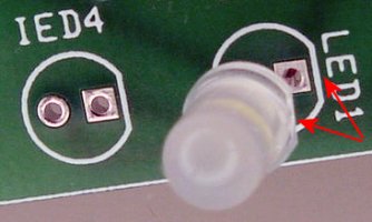 Insert an LED and or infrared emitter (IED) with the flat side (cathode) of the package matching the flat side of the silkscreen outline. LEDs LEDs are polarized parts and should be inserted such that the flat side (cathode) of the part package matches the part outline on the PCB. If for some reason the part doesn't have a flat (or you have covered it with shrink wrap tubing) you can simply test it on a multimeter (see pages 148-152 of Robot Building For Beginners) or with alligator clips (pages 156-159). To see if an infrared LED is lit up, you'll need to look through a digital camera. Bicolor LEDs (LED1 and LED2 on the motherboard) can be a little trickier, as they light up in a different color when flipped. For Roundabout, consider the cathode to be whichever lead is connected to GND (or -) when the LED lights up red. If you insert the bicolor LEDs in the wrong orientation (flipped), then they’ll light up green instead of red and red instead of green. You can either accept this, or desolder and flip them.  Zener diode inserted such that the band or stripe matches the straight line on the diode symbol on the PCB. Zener Diodes Technically, the zener diodes in Roundabout are optional and can be left out completely. However, zener diodes provide protection to regulated components (see pages 136-140 of Intermediate Robot Building), and zener diodes are really inexpensive. So, I recommend installing a 5.6V zener diode for ZD11 (motherboard) and ZD51 (daughterboard). Make sure to install the zener diode with the band/stripe matching the horizontal line (that the arrow is crashing into) on the diode symbol on the PCB. The robot won't work if you insert the zener diode in the wrong direction.  Molex connector inserted with strain relief / polarizing tab matching the outline on the PCB. Molex Connector Molex KK connectors have a strain-relief/polarizing/locking tab to make sure the connection is made correctly and stays in place. Be sure to insert the Molex connector such that the tab matches the outline on the PCB. You can substitute a different type or brand of connector with 0.1 inch spacing if you choose. A lot of builders use plain male square headers or female sockets (see page 345 of Intermediate Robot Building). Alternately, you can save money by soldering wires directly to the board. However, it makes debugging and disassembly more difficult. Also, you can't as easily swap in different brains like the Sandwich-Roundabout retrofit. ROUNDABOUT MOTHERBOARD Since this book and project is targeted for the intermediate builder, step-by-step instructions for installing resistors, connectors, and other parts should be unnecessary. Instead, this section concentrates on tips and options. However, if you have a question or would like for me to provide more information about installing a particular part, please don't hesitate to ask. I have made about ten copies of Roundabout so far. I begin by opening up the parts list spreadsheet and sorting by Column D (Description). This bunches similar parts together. Sometimes I'll hide columns G through T, such that the Quantity Per Full Roundabout (Column U) is viewable onscreen at the same time as the part description. This makes it easy to pull the exact part and quantity from storage.  Completed Roundabout motherboard with all optional components. Ready for the daughterboard. After getting all of the parts together, I'll grab one of the completed boards to act as a visual guide. See the picture above. What follows are instructions and tips for components that exist specifically on the motherboard.  Schottky Diodes Diodes are polarized parts. Be sure to install them such that the band/stripe matches the outline on the PCB.  VR11 Voltage Regulator The metal tab on the back of the TO-220 package of the voltage regulator must match the PCB outline. |
 IC3 and IC4 Panasonic PNA4602M Infrared Detectors Important: This part has been replaced by the equally compatible Vishay TSOP4038. The half-sphere on the front of the detector package should match the outline on the PCB. Notice that the holes in the PCB are slightly askew to point the detectors slightly towards the sides. The detectors leads should be inserted all the way down to the metal flanges. Don't let the detector sit up much higher than that, as the long leads will be subject to more electrical noise, causing false detections.  N12 or Test Points One side of the motherboard has two holes labeled “+UN GND TP or Unreg N12”. These holes connect to the 9 V battery through the power switch. That makes these convenient test points for measuring the battery's voltage during operation. Alternatively, this could become the power supply connection for an external circuit, such as a bunch of LEDs that light up the robot's body. Here are three options:
 Overcurrent Protection with a Polymeric Positive Temperature Coefficient (PPTC) Device CB11 is near the power switch. This is the location for an optional overcurrent protection part (see pages 131-136 in Intermediate Robot Building). It acts as an automatic circuit breaker, preventing damage that would be caused by a short-circuit in either the motors or robot circuitry. Since PPTCs are relatively inexpensive ($0.50) and easy to install (non-polarized), I recommend you use one (see the right side of the above picture). However, if you choose not to, you can't leave these holes empty. Instead, solder a bare wire between the holes (see the left side of the above picture).  Reversed-Battery Protection Also near the power switch, Roundabout features three options for reversed-battery protection (battery's +/- connections flipped). Here are three options:
 IC DIP Sockets Electrically speaking, IC DIP sockets are not polarized. They work even if installed in a flipped orientation. However, that may cause you to install the IC chip in the wrong orientation, which won't work and will likely damage the chip. So, be sure to install all IC sockets such that the notch matches the PCB outline. Also, be sure to install the IC socket directly over the PCB outline, and not to one side or the other. Some people choose to solder chips directly to the boards without using a socket. However, it is easier to debug (remove/swap a chip for testing) and easier to repair a board that includes sockets. IC1 Big Decision IC1 on the motherboard presents you with your most significant choice. Do you plan on adding the daughterboard to your Roundabout robot? Or is this motherboard going to be used standalone? If you are not going to use a daughterboard, then go ahead and solder a 14-pin IC socket to the IC1 location on the motherboard. If you are going to use a daughterboard, then skip the 14-pin IC socket and follow the instructions on pages 343-355 of Intermediate Robot Building for adding boardmount sockets. Yes, you can always change your mind and desolder one part and replace it with another later on. But, frankly, I always start with the boardmount sockets (not the IC socket) and test the standalone motherboard using a wire-wrap DIP socket as shown in Figure 16-8 on page 347 of Intermediate Robot Building.  Sneaky Jumpers JMP1 and JMP2 Sitting beside IC1 are locations for two jumpers. Normally, the bicolor LEDs (LED1 and LED2) and wired to the same outputs and the motor driver controls. As such, the LEDs always turn red or green depending on whether the associated motors are going forwards or backwards. With the microcontroller installed, I want the robot to be able to light up the LEDs even when the motors aren't turning. So, I added these sneaker jumper locations (JMP1 and JMP2) to disconnect the LEDs from the motors. That means you've got to make a choice. If you plan on only using the motherboard by itself, then go ahead and solder a bare wire in JMP1 and JMP2. But, if you plan on attaching the daughterboard at some point, then solder two-pin male headers in JMP1 and JMP2. These headers will let you decide when to tie the LEDs to the motors (add shunts -- yellow things in the picture) and when to let them function independently (remove shunts). 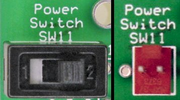 Power Switch There are two options for the power switch:
|
|
ROUNDABOUT DAUGHTERBOARD Compared with all of the tips and options available on Roundabout's motherboard, the daughterboard is a breeze!  Completed Roundabout daughterboard.  Sea of Holes There appears to be a sea of holes surrounding IC51 on the daughterboard. The top row and bottom row of holes are unused on the ready-made boards and can be ignored or used as test points. The row just above the IC outline and just below the IC outline (highlighted in red in the picture) are for soldering the IC DIP socket. The remaining two rows (highlighted is dotted yellow in the picture) are for soldering the male headers from below as described on pages 343-355 of Intermediate Robot Building.  Pushbutton SW65 The daughterboard has a location for the pushbutton. Only the top two pins of SW65 are connected to the circuit. It is important that you find the two pins on your pushbutton that are open (infinite resistance) when the button is not pushed, but that are closed (shorted, zero resistance) when the button is pushed. The easiest way to find the correct pins is by using a multimeter. If you happen to solder a two-pin pushbutton to the bottom holes, or solder a four-pin pushbutton with the top two pins always open or always closed, then the robot won't be able to read the pushbutton presses (but no damage will occur). ROUNDABOUT FLOORBOARD Being the smallest board with the fewest components, the floorboard is the easiest to put together.  Completed Roundabout floorboard.  Cutting to Shape The floorboard fits inside of Sandwich's Ziploc body or on a 6-inch diameter disc without needing to be cut. But, depending on the shape and radius of your Roundabout robot, you may want to cut the corners of the floorboard (see pages 380-381 of Intermediate Robot Building) to prevent the portions from sticking out of a round body. In any case, be sure to perform any desired cutting before installing components or soldering. Position the floorboard where it is going to be located on the robot and mark the outline of the portion that sticks out. The two white lines on the corners of the ready-made board indicate safe areas to cut. Beyond that, double-check before cutting that you aren't going to snip any circuit traces. (For example, I chose to cut a little bit deeper in the above picture, actually entering the potentiometer outline.) I used a table saw with a diamond blade to make straight cuts, but shears are also popular for cutting circuit boards. A Dremel with a cut-off disc can be used in a pinch. Always wear a breathing mask when cutting or drilling PCBs. 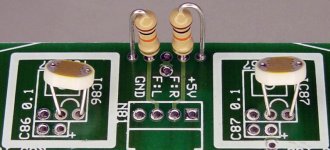 Optional Photoresistors After reading pages 376-378, if you are still not deterred from using photoresistors, then you can actually substitute photoresistors for TSL257s on the floorboard. Insert the photoresistor leads where the little half-circle appears inside of the TSL257 outline (see above picture). IC86, C86, IC87, and C87 are not necessary if you're using photoresistors. However, you'll need to add two 10 kilohm resistors as shown in the above picture. HOW TO PROCEED Here are the steps I go through to build Roundabout after the body is complete and the motors are installed:
Good luck! Enjoy! Let me know if you have any questions. |