(article continued from previous page)
Now that the rings are machined, the test apparatus can be completed with a few additional parts.
The polarizer test wheel is best turned by hand when trying to quickly find the peak voltage to align the polarizing film. However, I thought it would be cool to use a motor to smoothly roll through an entire rotation and display the results on an oscilloscope.
Most motors have screw holes on the front to mount the motor to a bracket. For whatever reason, the extremely-heavily-geared motor (2050:1) that I selected for the polarizer test apparatus lacks motor mounting holes. The solution is to grasp the motor in a motor clamp mounting block.
The tire on the motor needs to press firmly against the polarizer wheel. I suppose this could be accomplished with very careful positioning of the motor mount. However, the homemade hub is probably not perfectly round, meaning contact between the tire and the wheel might become too tight or too loose as the wheel rotated around. Also, what happens as the tire and wheel wear down?

A spring-mounted motor making constant contact against a larger wheel with a rubber band for traction.
A creative solution is to mount the motor with a hinge and to use a light spring to keep the motor tire firmly against the polarizer wheel. This has the added advantage that the spring can be quickly disconnected and the motor swung away to turn the wheel by hand.
This technique is also applicable for inexpensive robots that don’t use gearmotors. You can have a plain motor shaft (without a wheel) press against a large homemade wheel with rubber band traction. You can even use a rubber band instead of a spring.
The ratio between the small-diameter motor shaft and the large-diameter wheel will provide an increase in torque and a decrease in speed -- just like a gearmotor would.
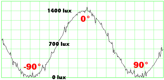
The first test consisted of a commercial photometer stuffed into the box, a big lightbulb with a polarizing filter providing the polarized light source, and the gearmotor smoothly turning the wheel with a polarizing filter taped to it. The output of the photometer was measured on an oscilloscope.

An oscilloscope trace of voltage and light levels produced by an unamplified photometer in a polarizing film test apparatus.
The photometer output is unamplified and the fairly weak. Thus the trace is a little noisy (jagged). I should have added a low-value capacitor.
This graph shows that when the polarized filters are lined up at the same angle (0 degrees of difference in angle, aka parallel) the maximum amount of light passes through. However, when the filters are orthogonal to each other (90 degrees out of alignment, aka crossed) the least amount of light passes through.
The angles in-between produce a sinusoidal change in the amount of light passed. If the angles in between had produced a linear change, the waveform would have looked triangular instead of curvy.

Front view of a polarizing film test apparatus. Notice the photodetector component centered inside the hole.
The photometer was then replaced by a TAOS TSL257 light-to-voltage converter on a solderless breadboard. Spacers beneath the breadboard position the TSL257 detector in the approximate center of the wheel hole.

An oscilloscope trace of voltage levels produced by a TAOS TSL257 photosensor on polarized-film test equipment.
Because the TSL257 component is internally amplified, the signal to the oscilloscope is strong and clean. The trace almost looks too perfect. However, I can assure you that these are the actual results.
This second graph with different equipment confirms that the amount of light passing through a pair of polarizing filters can be represented mathematically with a trigonometric function. (That is, the TSL257 confirms that the photometer wasn’t generating a modified output.) Since the maximum value occurs at 0 degrees, this is best represented by a cosine.
Light passing percentage of maximum = (cosine(angle in degrees * 2) / 2 + 0.5)*100All of this might solicit a “who cares”. But, suppose you want to know how far out of alignment your robot’s sensor can be and still receive 99% of the maximum signal from the beacon.
Angle in degrees = arccosine(((percentage / 100) - 0.5) * 2) / 2It turns out that the sensor can be misaligned (tilted) by ±5.74 degrees from 0° and still receive 99% of the maximum beacon signal. And, conversely, the sensor can be misaligned ±5.74 degrees from 90° and only detect 1% of the maximum value of the other beacon.
This means that you can align the polarizing film by eye, without too much of a detrimental effect. And, if you carefully align the polarizing film by a more precise method (such as this test box), your robot will have that much more tolerance for bouncing around as it competes.
Finally, let’s see what a sensor board would look like for detecting the polarized beacons.