

To this point, I’ve put together a nice rig with an automated photo rail to take close-up photos with crisp focus. But, there is something I’ve left out... lighting.
The next two photographs are extreme close ups of a home-etched printed circuit board. Both photos use the same board, same lens, same camera, same tripod, and same settings. Which image do you prefer?
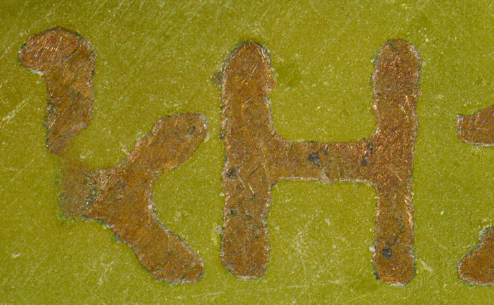
PCB close up YA24 NAN5M lens built in LEDs
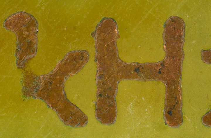
PCB close up YA24 NAN5M lens
The second image is certainly more attractive and it better matches what I see with a magnifying glass when I look at the subject. Yet, if the purpose of the photograph is to detect scratches and staining, then the first image is more useful.
In all fairness, I cheated a little bit by blowing off the dust between shots. But, more significantly, I added a custom ring light and partially backlit the second image. The point is, with everything else being equal, lighting makes a huge difference! If you’re not getting what you want, adjust your lighting.
The first image was taken with the lighting cover included with the Yasuhara lens. It consists of three LEDs powered through a USB port. The effect is a little harsh.

Yasuhara Nanoha LED lights
The second image was taken with a homemade ring light with a 3D printed sleeve to snugly slide onto the Yasuhara lens with their lighting cover removed. The homemade ring light has 24 LEDs (Vishay VLHW4100) arranged in 8 groups of three LEDs. I chose through-hole LEDs rather the surface mounted, in order to bend the LEDs to aim at the tiny target.

Homemade ring light with selectable LEDs
The homemade ring light has four advantages:
As with the shutter circuit, the ring light was laid out in a PCB program.

Ringlight in PCB layout program
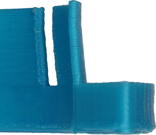
Here is the ring light before snipping the LED leads, and before attaching the 3D-printed holder.

Homemade ring light soldered but not snipped
There are three screw holes tapped into the sleeve to attach it to the ring light PCB. Because the screws are small (2-56) and don’t require significant holding force in this application, the threads are not at risk for ripping out of 3D printed ABS.

3D printed ring light sleeve
I am particularly proud of the taper in the sleeve, which gently presses against the Yasuhara Nanoha lens. I had low expectations for the taper -- as such small details usually result in a failed print.
Tapered 3D printed for friction hold
Because I wasn’t sure how this was going to turn out, I prototyped the LED driver circuit on a solderless breadboard. There are eight sets of three LEDs in series. That means that they need about 9-10 volts @ 20 mA for each group of three, and (20 mA x 8) = 160 mA for all eight groups.
Rather than fiddle with trimpots, I experimented with Microchip CL2N3-G current limiting drivers. Although it is awesome to have a 20 mA current limiter chip in a TO-92 package, it has a significant dropout voltage that I didn’t see in the datasheet.

Prototype LED ring light driver
Here is the total setup.

Nano with XY stage StackShot and ring light
Great! I now have a reliable setup for taking macro images. It conclusively beats an old toy microscope. But, uh oh, what about a modern toy microscope?