To obtain the power supply graphs on the previous page, I didn’t stand outside for two days straight measuring the power sources with a voltmeter. Instead, the circuit itself is able to independently monitor the power sources with the addition of a few resistors.

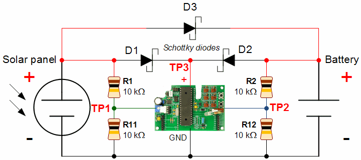
Schematic of solar panel charger circuit with voltage measurement.
Diodes D1 and D2 prevent the power source voltages from directly affecting each other.
Although diode D3 allows the solar panel voltage to charge the batteries, measuring the voltage behind D2 does indeed reflect the battery voltage, not the solar panel voltage. (Well, assuming there is a battery pack connected.) If you pull the batteries out of the circuit and measure them with a multimeter, the voltage would be nearly the same as the in-circuit measurement.
The device performing the measurement needs to have a fixed voltage (either regulated power or a voltage reference). In this example of the weather station device, it has a linear regulator that supplies 3.3 V to the microcontroller. As such, we need the measurable voltages of the power sources to be less than 3.3 V in order for the microcontroller analog-to-digital converter (ADC) to be able to safely and accurately measure the power supplies.
The power source voltage is easily divided in half using a voltage divider consisting of two equal value resistors in series. In this case, R1 and R11 are 10 kilohms each, so the voltage in the middle of them will be half the voltage that is being fed into the top.
For example, when the solar panel is at 5.65 V (the maximum peak I measured in full sun with no load attached to the panel), TP1 will measure 2.825 V. That’s less than 3.3 V, so the microcontroller can measure it accurately. After measuring, the microcontroller simply multiplies the value by 2 to determine the true solar panel voltage.
If the device is disconnected at TP3 (for example, by an on/off switch at that point), one might be concerned with power injecting itself into the circuit through TP1 and TP2. Or, even worse, what happens if the solar panel is installed upside down? A negative voltage would be present at TP1. The voltage measurement test points are not protected by the diodes.
It isn’t a big deal because the resistances of R1 and R2 are high enough that very little current can flow. In order to damage most electronic components, there usually must be a relatively high voltage (static electricity perforating a semiconductor layer) or concentrated current (melting a bonding wire).
A power source at 5 V would only produce 0.0005 A (half a milliamp), at worst, through a 10 kilohm resistor. The device itself would add additional resistance, cutting current flow further. This small amount of current will not damage a modern microcontroller, particularly because it contains diodes to clamp the excess voltage.
If resistors R1 and R2 provide current-limiting protection, then why not increase their resistances above 10 kilohms? In order for the analog-to-digital converter to work accurately, the input source impedance should be as low as possible. The compromise between protection, power usage, and accuracy is to pick 10 kilohms. (The Atmel datasheet says “The ADC is optimized for analog signals with an output impedance of approximately 10 kΩ or less.”)
If you really needed to, you could improve accuracy by:
A disadvantage of using a couple of resistors to measure battery voltage is that current is constantly flowing through them -- using up power. In this example, we have a 5 V power source flowing through 20 kΩ (10 kΩ resistor + 10 kΩ resistor). Using Ohm’s law, we see that each voltage divider uses 250 µA or 0.25 mA.
In a low-current or power-conscience device, you can connect the bottom of the voltage divider to a low-saturation-voltage transistor like a Zetex ZTX688B or ZTX1048A. The microcontroller would then turn on the transistor before measuring the battery pack and solar panel voltages, and then turn off the transistor to stop wasting power.
Solar panels degrade over time. Most manufacturers quote around a 20 year lifespan, albeit with reduced output along the way.

Panasonic BP-378234 solar panel becoming dirty.
The solar panel photographed above is exposed to the elements. Due to five days without rain, the panel has accumulated dust, tree sap, and possibly bug spit. Much like the solar panels on the Mars Rovers, I hope the environment will occasionally clean off the panel. (For the winter, the solar panel has been moved into a watertight project case.)
During the winter, colder temperatures increase the efficiency of solar panels. But, reduced sunlight may more than negate any improvements from cold weather -- especially if you don’t clear the snow off every day.
Battery leakage current (self-discharge) should slow due to colder temperatures. However, battery capacity and peak current capability will be reduced.
It will be interesting to see if a carefully matched panel and battery pack are not equally suited to survive the winter together. It may be that seasonal changes to a higher-capacity panel and higher-capacity (or different chemistry) battery pack are required.
Results: Solar recharging in the winter.
Trickle charging a battery every day probably won’t produce the optimal battery longevity; however, a remotely-located device will run for much longer than it would with non-rechargeable batteries. Watch the voltage levels over long periods of time to see if the top battery voltage decreases or the voltage drops faster overnight, which would indicate a loss of battery capacity.
Obviously, using a couple diodes for a charging circuit must have some drawbacks, otherwise fancy chargers wouldn’t exist. Still, we can see that three diodes are all it takes to make a reasonably functional rechargeable battery-backed solar power source.