

I have a $500 Rigol DP832 programmable triple-output power supply sitting on my bench, yet I built a 5V regulator to sit atop a 9V battery for some reason. Perhaps it’s more portable, or cheap enough to toss in with the rest of the project it is powering, or maybe the bench power supply is just overkill. Or maybe, just maybe, I saw other people making them and I thought it would be cool to build myself.

Five volt regulator cap for nine volt battery
Two boards were used to enclose the circuitry and to allow the power switch to stand out on its own. Also, the board connection pins are power points. So, you can use the hookup loops, board interconnect pins, header connectors, or wire holes to connect the power supply to your project.

Test leads supplied power by loops or interconnect wires
The circuit is not fancy. It’s just a classic linear voltage regulator.

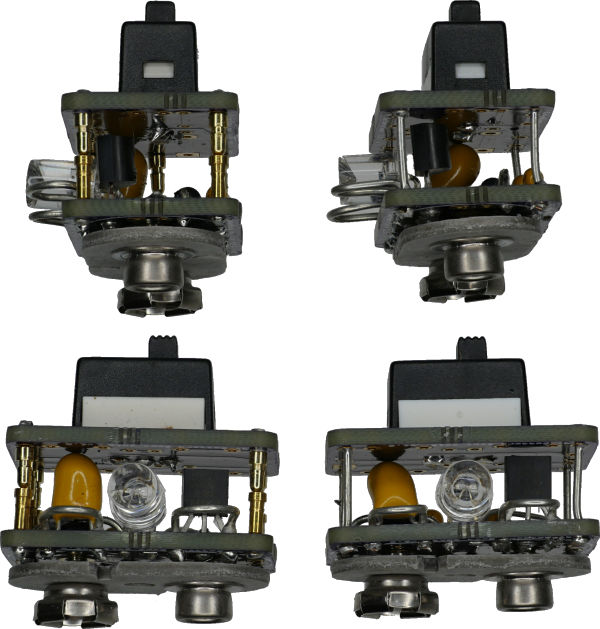
Top of 9V to 5V regulator board
D1: Prevents damage due to connecting the battery backwards. Any small signal diode will do, because the current output of the TO-92-sized regulator is fairly low and the voltage drop between 9V and 5V is large enough to be unaffected by the diode voltage drop.
C1: 0.1 µF capacitor on the battery input
C2: 0.1 µF capacitor on the regulator output.
C2bulk: 1 µF or larger capacitor on the regulator output. All three capacitors stabilize the regulator output as the project consumes different levels of power during operation.
IC1: The voltage regulator that converts between the unregulated 9.6 volts to 7 volts from the battery into a steady 5 V or 3.3 V or whatever is desired.
R1: Resistor that limits the amount of current provided to LED1. Usually between 220 ohms and 470 ohms. In this case, LED1 is a flashing LED that does not need a current-limiting resistor, so a wire is used instead.
LED1: Power indicator LED. This is to avoid forgetting to turn off the regulator when not in use. The regulator uses a certain amount of power even when idle.
I chose a flashing LED in this case to draw more attention to the fact that the power supply is turned on. Also, a flashing LED uses less power than a steady LED, because a flashing LED is off part of the time.
This particular LED is unusual in that it has a concave lens. Supposedly, such a shape provides a wider viewing angle. (Unfortunately, I don’t have a part number for this, as it came from a lot sale on an auction site a while ago.)

Concave lens LED
The bottom of the lower board has the battery snap. The top of the lower board has the regulator circuitry. The bottom of the upper board is empty except for circuit traces. The top of the upper board contains the power switch and connection points.

Regulator by layer
The upper and lower boards can be connected with plain wire or interconnect pins. The plain wire is permanent but inexpensive.
Connectors versus solid wire
The interconnect pins allow the boards to be separated to make future soldering of wires and connectors easier. In hindsight, if I had used longer pins and shorter components, the upper board could be removed and the battery circuit could be placed upside down on a solderless breadboard for instant prototyping.

Gold interconnect pins
It was surprisingly difficult to keep the boards completely parallel during soldering. I ended up holding them together with rubber bands and mounting them in a vise.

Keep boards square by soldering in vise with rubber bands
If you’re using plain wire instead of connectors, you need to make sure you are completely finished soldering the boards before soldering the pair together.
The 9V battery snap is a Keystone Electronics #967. The studs are machined to provide a slight gap between the snap insulator and the PCB.

9V snap peg has larger diameter to provide space
This allows the board area above the snap to be populated with through-hole components (whose leads will protrude slightly below the bottom of the board).

Gap between bottom of board and snap insulator
Alternatively, you can carefully remove the top from a used 9V battery instead of buying a snap connector. You’ll need to trim the excess strip connector to prevent shorts on the bottom of the PCB and the strips aren’t going to be as strong as studs.

Battery snap removed from discharged 9V battery
In either case, the components must first be soldered in place and the leads trimmed. I also like to reheat the trimmed leads to round them off a bit.

Solder clipping and reheating
Speaking of battery, I like the look of the Rayovac heavy duty batteries. These batteries are zinc-carbon rather than alkaline, so they’re garbage. I know of no advantages other than they look pretty.

Rayovac heavy duty 9V batteries D1604 4TD
I tried painting an alkaline battery to look equally attractive, but without the branding. I gave up halfway for obvious reasons.

Home painted battery is awful
Now that I have these 5V power sources available on my desk, it will be interesting to see the advantages and disadvantages of the designs under real world usage. I suspect I’m going to want to make a second generation with a 3D printed cover, to avoid stray parts from shorting exposed contacts.
The design did not end up as attractive as I envisioned in my head. The rounded corners of the PCB are nice. The stacking of PCBs produces an aligned space, but the through-hole components inside look messy and create too tall of a structure. The switch on top is also too tall functionally, although I like the visual line it produces. The attachment loops don’t stand out enough -- perhaps they need some color or better labelling.