

Occasionally, you'll need to measure electronic parts with very low resistances, such as wires, switches, current-sense resistors, fuses, relays, or igniters. However, most multimeters aren’t accurate below 1 ohm, and some can’t even measure accurately below 10 ohm. Rather than purchasing a special four-wire or low-resistance ohmmeter, you can reasonably measure down to 10 milliohms or less with a common multimeter in millivolts mode.
By the way, this experiment began when I incorrectly stated in the rocket launcher examples that I didn’t have the ability to accurately measure the resistance of 12 AWG cable.
To measure low resistance, you'll need:
Obviously the accuracy of this measurement depends on the accuracy of the meter. But, most multimeters are reasonably accurate.
The 5 V power supply needs to stay reasonably steady between readings. Any fluctuations will introduce some inaccuracy. Almost all regulated supplies are excellent under these conditions:
Surprisingly, it doesn’t matter if the power supply voltage is accurate (exactly 5 V). Any value between 4.5 V and 5.5 V is fine, as long as it is steady.

Low resistance measurement circuit on a solderless breadboard.
This circuit is a simple voltage divider where the same amount of current passes through R2 as passes through R1. We will measure the voltage across each resistor. That provides us all of the information we need to calculate the resistance of R2, based on the ratio of the voltages and the known resistance of R1.
In the above photograph, R2 is a standard 10 ohm through-hole resistor. However, you can replace R2 with alligator clips attached to wires so that anything (cables, igniters, and surface-mount resistors) can be measured instead.
R1 is the “known resistance” in this circuit. A high wattage, low-temperature coefficient resistor is best. But, even a standard 5% resistor is acceptable for most hobbyists.
According to Ohm’s law, 5 V passing through a 220 ohm resistor is 0.114 watts of power (just over 1/10 watt). That energy will be released as heat in the resistor.
As the resistor heats up, its resistance value changes slightly. Low-temperature coefficient resistors (±50 ppm or less) change value less than ordinary resistors (±100 ppm or greater). Higher wattage resistors are usually capable of dissipating more heat, which also will reduce resistance changes.
Since the accuracy of this circuit depends on the resistance staying steady, you want to use the highest wattage, lowest-temperature changing resistor that you can for R1.
You can buy a Vishay/Dale 1% tolerance (accurate) 1/2 watt (dissipates heat) 50 ppm (low temperature change) 220 ohm metal-film resistor for $0.12 from Mouser (71-CMF60220R00FHEK). Or, you can buy a more temperature stable Ohmite 1% tolerance, 3 watt, 20 ppm, 220 ohm wirewound resistor 43F220E for $1.14 from Digi-Key.
To prove this measurement works with even the most humble resistor, I chose an ordinary 5% tolerance, 1/4 watt, ±350 ppm, 220 ohm carbon-film resistor from my assorted collection of resistors.
Regardless of the resistor you select, before installing R1 in the circuit, measure it using the resistance (Ω or ohm) mode of the multimeter. Do NOT measure the resistance when the resistor is installed in a circuit -- it will produce an inaccurate reading. Instead, measure the resistor by itself (remove it completely from the breadboard if you already installed it).
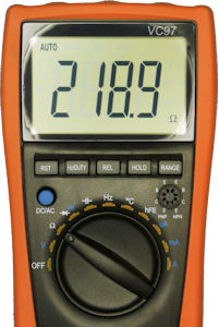
Multimeter measuring known resistance.
Surprisingly, it doesn’t matter if the resistance value is plus or minus 5 percent. In fact, any value from 200 to 240 will do, as long as the resistance stays steady.
Write down the measured resistance value of R1 and place it in the breadboard. My resistor is 218.9 ohms.
For the first test, we’re going to measure the resistance of a resistor that can also be measured by the multimeter. That way, we can check that our math and circuit are working correctly before we try some really low resistances. Let’s start with a 10 ohm resistor in the breadboard for R2.
With power turned on, measure the voltage across R1 using the DC volt measurement mode of the multimeter.


Measuring the voltage drop across the known resistor in volt measurement mode.
My R1 voltage measured 4.7696. Since R1 has a much larger resistance than R2, it follows that R1 should have a much larger voltage drop than R2. The value should always be above 4.5 V.
Next, we’re going to measure the voltage across R2. Because this value is going to be much smaller (usually less than half a volt), you'll want to use a multimeter that includes a millivolt (mV) measurement mode. If you use the standard volt measurement mode, it won’t be as accurate and may not provide enough decimals places. Fortunately, most multimeters include the millivolt measurement feature.


Measuring the voltage drop across the unknown resistor using millivolt measurement mode.
My R2 measurement is 216.64 mV (0.21664 V).
Now, here’s the magic formula:
			R2 in ohms = R2 millivolts / 1000 / (R1 volts / R1 resistance)

			R2 in ohms = 216.64 mV / 1000 / (4.7696 volts / 218.9 ohms)

			R2 in ohms = 9.94 ohms
That’s a reasonable value, given that the 5% tolerance says the resistor can be from 10.5 ohms to 9.5 ohms.
The formula says the resistor is closer to 9.9 ohms than 10 ohms. What does the multimeter say?

Multimeter measuring initial test resistor in ohms mode.
The multimeter agrees. Fantastic!
Now let’s try some resistances that are low enough that the multimeter can’t measure them accurately in ohms mode.

Examples of low resistance parts such as resistors, cable, and igniters.
When measuring the voltage across R1 or R2, be sure to place the multimeter test probes as close as possible to the start and end of the item being measured. You don’t want to include the resistance of the breadboard sockets or alligator clip wires.
Given a 218.9 ohm or †219.2 known R1 resistor, here is what I measured and calculated:
| # | Description | R1 Volts (measured) | R2 Millivolts (measured) | R2 Ohms (calculated) | Expected |
| 1 | 10 ohm 5% tolerance common resistor | 4.7696 | 216.64 | 9.94265 | 9.5 to 10.5 |
| 2 | 0.2 ohm 5% tolerance current-sense resistor | 4.9816 | 4.575 | 0.20103 | 0.19 to 0.21 |
| 3 | Estes model rocket igniter | 5.023 | 13.884 | 0.60505 | 0.6 or 0.8 |
| 3 | Quest Q2 model rocket igniter | 4.9114 | 74.1 | 3.3071† | 2.5 or 4 |
| 4 | KOA NPR2 10 mΩ 10% tolerance current-sense resistor | 5.0372 | 0.234 | 0.01016 | 0.009 to 0.011 |
| 5 | 59 feet (2 × 29.5) of 14 gauge stranded copper wire | 4.965 | 3.48 | 0.15342 | 0.13629 to 0.1593 |
| n/a | 34 feet (2 × 17) of 24(?) gauge Estes stranded copper wire | 5.019 | 18.019 | 0.78588 | 0.71672 to 0.88706 |
Awesome! All of the measurements came within the expect range.
Based on the multimeter test results, I used my most accurate resistance meter (the VC97) to measure the value of R1. Any error in this measurement will affect all of the test results. So, you can double check the accuracy of R1 by measuring the voltage and the current flow to calculate the true resistance after the temperature stabilizes.
I repeated a few of the tests after the known resistor (R1) had cooled overnight. The results were about 1% different. After resistor R1 warmed up, the results were improved (fairly similar to initial test results). This indicates that accuracy is affected by temperature.
It turns out that the resistance of my ordinary carbon-film resistor dropped upon heating, from 218.9 ohms to 217 ohms. I determined this by measuring the current until it stabilized (R1 heat-up temperature plateaued), and then measuring the voltage across R1.
4.88 V / 0.022488 A = 217 ohms
Therefore, it would be best to:
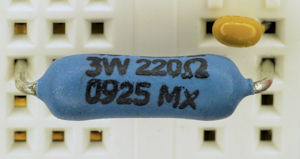
Ohmite 3W temperature-stable 220 ohm resistor.
In fact, after substituting in the higher-wattage temperature-stable resistor recommended earlier in the article, the resistance of R1 changes by less than one-tenth of an ohm.