

While cleaning out my basement, I ran across my old Commodore 64 computer and Atari VCS 2600 game console. The joysticks compatible with those machines have industry standard DB-9 connectors and internals consisting of simple switches. Unlike modern joysticks with fancy proprietary serial interfaces, these classic controllers are very easy for a hobbyist to connect to homemade electronic devices and robots.
I thought it would be fun to show readers how to build a wired remote-controlled robot with an Atari joystick. You can build this project with a few transistors, resistors, diodes, and a single 14-pin DIP motor driver chip. You don’t need a microcontroller or even a voltage regulator.
Along the way, I'll show you how to modify a Solarbotics GM7 motor for easy mounting. The end of this article includes movies of the completed robot in action.

A simple robot controlled by an Atari joystick.
The basic robot consists of an Atari joystick, Lego wheels and Lego bricks, off-the-shelf electronic components, Solarbotics GM7 gearhead motors (or Lego motors), and a pack of 4 AA batteries. Of course, you may invent your own variation.
The above photograph shows a robot that includes a printed circuit board (PCB). But, you can put the control circuit together on a solderless breadboard if you prefer.
Depending on your age, you may have some Commodore or Atari joysticks in your basement.
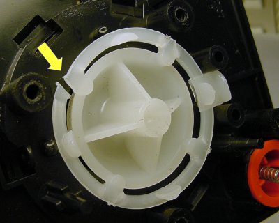
A broken rigid plastic ring in an Atari 2600 joystick.
Unfortunately, depending on how much you played with the joystick, it may be broken.
The Atari’s tall stick permits too much force against the mass-produced internal plastic parts. The repeated stress eventually cracks the semi-flexible ring. (Modern joysticks and controller pads are short and flat to avoid significant torque and to permit players to change directions quickly.)
If you hear a clicking sound when you move the stick up, down, left, or right, the plastic ring attached to the joystick handle is likely cracked. Sometimes the joystick will still work well enough. However, the break may cause malfunctions that you might mistakenly blame on your electronic circuit.
Fortunately, there are a couple of solutions.
First, believe it or not, Atari joysticks are still being manufactured today! You can get a completely new joystick (without the orange paint or rubber feet) from eBay. However, the price with shipping is a little steep.
Alternatively, you can buy a bunch of old joysticks from eBay or a second-hand store (along with the computer or game console if you’re nostalgic). Even if some of the joysticks are broken, you might be able to swap parts.
Important note: For this project, you can’t use the recent Atari or Commodore joysticks that include built-in game emulators. They’re much more complex and don’t have the same outputs.
If you’re really desperate, you can simply build a board with a bunch of pushbuttons, as we’re about to see...

The PCB inside of an Atari joystick consists of five simple buttons.
The circuitry for the Atari and Commodore joysticks (and compatibles) consists of five buttons: up, down, left, right, and fire. The joystick communicates diagonal moves with multiple buttons pressed simultaneously, like up and left at the same time.
The original Atari and Commodore joysticks (as opposed to later models or third-party sticks) don’t even receive power. It’s just a bunch of switches connected to ground.
Ignoring fire (which can be pressed on its own at any time), the four directional buttons produce sixteen possible states:
| Up | Down | Left | Right | Desired Robot Action | Left Motor | Right Motor |
| off | off | off | off | idle | coast | coast |
| off | off | off | on | spin clockwise | forward | reverse |
| off | off | on | off | spin counter-clockwise | reverse | forward |
| off | off | on | on | stop | brake | brake |
| off | on | off | off | reverse | reverse | reverse |
| off | on | off | on | reverse veer right | reverse | coast |
| off | on | on | off | reverse veer left | coast | reverse |
| off | on | on | on | stop | brake | brake |
| on | off | off | off | forward | forward | forward |
| on | off | off | on | veer right | forward | coast |
| on | off | on | off | veer left | coast | forward |
| on | off | on | on | stop | brake | brake |
| on | on | off | off | stop | brake | brake |
| on | on | off | on | stop | brake | brake |
| on | on | on | off | stop | brake | brake |
| on | on | on | on | stop | brake | brake |
Of course, some of the above combinations are impossible for a joystick. For example, you can’t press left and right at the same time, unless your joystick is seriously broken.
The associated motor directions would be fairly easy to program using a microcontroller. However, I promised that this article wouldn’t use a microcontroller.
After a lot of thought, I figured out a fairly complex circuit to produce these outputs using standard logic chips. To avoid using a voltage regulator, I selected a bunch of semi-obsolete 4000 series CMOS chips. But, that seemed too convoluted and contrived.
In the end, to simplify the circuitry as much as possible without losing decent functionality, I decided to create a subset of five most-important robotic actions:
| Up | Down | Left | Right | Desired Robot Action | Left Motor | Right Motor |
| off | off | off | off | idle | coast | coast |
| off | off | off | on | spin clockwise | forward | reverse |
| off | off | on | off | spin counter-clockwise | reverse | forward |
| off | on | off | off | reverse | reverse | reverse |
| on | off | off | off | forward | forward | forward |
The above table can be implemented in a circuit with three conditional statements:
Check through my logic to make sure you agree that all five actions in the table can be properly implemented with those three conditional statements.
Also, note that in all three conditional statements the buttons are combined with the word “or”. This is purposeful, because combining grounded switches with OR logic can be accomplished using diodes.