(article continued from previous page)
The first step of machining the Sharp distance-sensor tester is to design everything in a two-dimensional drawing on the computer. By thinking through the layout first, I didn’t waste material or machining time. Additionally, the key parts (such as the Sharp sensor and the end of the level) can be held against the printouts to perform a quick sanity check of dimensions.
The next step is to select raw stock.
I chose black ABS plastic for the sensor bracket to avoid light from behind from altering the sensor values. Additionally, ABS is inexpensive, easy to machine, and is readily available in sheets/plates of the desired thickness. The ABS plastic was purchased from McMaster-Carr.
I chose acetal (Delrin) for the slide because it is slippery, which will reduce wear on the level. Additionally, acetal is a fairly dense plastic (about 40% more dense than ABS) and I wanted the slide to have some mass to resist tipping. The brown acetal block came from scraps sold on eBay.

Raw material is machined to major dimensions and compared to the CAD drawings.
Before performing the more complex machining, the raw material is machined to the desired dimensions and the edges are squared up. In the above photo, the workpieces are compared against the drawings before proceeding.

Left: DRO on milling machine is zeroed by using an indicator with a light. Right: The workpiece sits on parallel blocks to obtain the necessary height to machine without hitting the vise.
My Microlux milling machine has a homemade digital read-out (DRO). However, these parts are simple enough that they could be made by simply taping the paper templates to the blocks or by drawing major lines on the blocks with a permanent marker (like a silver or black Sharpie marker).
Before placing the partially machined workpiece into the vise, the upper left corner of the vise is set to zero in the DRO by touching a lighted indicator to both edges -- one edge at a time. By doing so, I can simply look at the digital display to determine where the cutting bit is located on the workpiece.

Checking the dimensions of the workpiece with a digital caliper before removing the workpiece from the milling machine vise.
Have you ever been machining a masterpiece and accidentally turned the hand dials the wrong direction or overshot an edge? Oh no! It’s ruined!
Here’s a tip: Start by machining out the bulk of the piece without going all the way to the desired dimensions. That is, if you want to cut out 5 cm wide block that is 5 cm deep, leave an extra 1 mm margin (or whatever) in all dimensions by cutting out a 4.8 cm wide block that is 4.9 cm deep. Then, make your final cut with one only a single pass.
I was able to get the inner leg spacing of the slide to exactly the desired width by first cutting away the bulk of the inside chunk with multiple passes, before making one final pass to skim off the remaining portion to exact dimensions.

Drilling the acetal slide and ABS bracket.
Although a drill chuck can be used for light machining of soft materials like plastic, better tolerances and longer chuck life is achieved by using a collet chuck rather than a drill chuck when milling. Since swapping chucks is a bit of a pain, I get all the milling out of the way before swapping in the drill chuck for drilling all of the parts.

Pairs of parts can be made to the same dimensions by machining them at the same time.
Although it isn’t absolutely critical for this project, the slide pads were milled together so that their heights would be the same in relation to their screw holes. I was concerned that one side would be lopsided. But, the pads don’t make contact with the underside of the top of the level, so it didn’t matter.

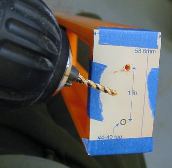
Hand drilling the end of the level with a paper template taped on it.
The 1:1 scale computer paper drawing indicates the screw holes for the end of the level. The printout is taped to end of the level and the holes are drilled with a #43 drill. The holes are then tapped for #4-40 screws.
After assembling the parts, I was pleased with the overall fit and alignment. No part is absolutely critical on this test equipment, but feels good to have a setup that is sturdy and smooth.
Plastic can be surprisingly difficult to mill perfectly, as it tends to flex and rebound slightly. Don’t be surprised if you have to cut slightly deeper than expected to account for the amount that the plastic contracts during machining and subsequently expands after the end mill has passed by. Holes sometimes need to be drilled with a slightly oversized drill for the same reason.
Now that the test apparatus has been machined, it is time to check how the Sharp distance sensor performs in comparison to the datasheet...