

A well-engineered kit from Parallax.
I received my Boe-Bot as a Christmas present. It takes only a few hours to build and few tools are necessary. I think I used a Phillips-head screwdriver, needle-nose pliers, and some wire cutters (for modifying the servo motors). No soldering!
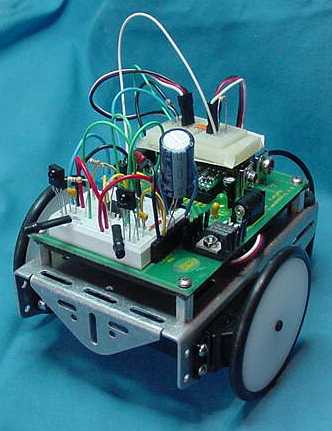
Boe-Bot front view
Notice the sturdy metal frame, with vacant locations for mounting additional equipment. High-quality material, all the way.
There’s a vertical gap between the main board and the frame. The power and motor wires run through the center of the frame and into the gap. Containing the slack of the wires within the gap makes the wires less susceptible to snagging on obstacles or blocking sensors. It also improves appearances.

Boe-Bot overhead view
The white breadboard (in the upper-right of the above picture) encourages modifications and experimentation. I notice a lot of robot hobbyists use wire-wrap or solder. I prefer a breadboard because my freeform building style requires constant refinements when I’m still learning.
There are additional connectors (black female single and double rows) for wires throughout the main board. There are multiple output connections for ground, regulated power, and unregulated power. The pins on the microcontroller are brought beside the white breadboard, for convenient access.
The main board was apparently designed before Boe-Bot, because the breadboard didn’t contain enough free slots to accurately implement the official schematic. Compromise wiring diagrams were included in the documentation, but I chose to tape an ugly mini-breadboard in the back. I give myself 5 points for technical merits; -5 points for aesthetics.
A standard serial port connector is located at the rear of the main board. This is much nicer than loose wires or proprietary connectors provided in some robot kits. Still, not as cool as LEGO MindStorms’s infrared port.
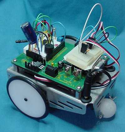
Boe-Bot side-rear view
There’s a little white ball located on the back to act as a pivot point. When one of the motor-powered wheels rotates faster than the other, the white ball is dragged a little in the turn. When both wheels are rotating equally, the white ball rolls freely forward (or backward) on its pin axle. This promotes straight movement, while permitting turns. A definite improvement over glide pads that are always dragged.
Notice that the white ball is on the rear of the robot, not the front. For these body shapes, it’s easier to pull straight than to push straight. Pushing requires a little more torque in guidance, whereas pulling just requires the object to follow due to the physical strength of the connecting material.
To me, the manual modification of the motors and the mounting of the wheels was by far the most demanding portion of building. I was anxious about the possibility of wrecking my motors when I cut away the plastic gear stops. And, I still don’t think both wheel hubs are firmly (or squarely) mounted in the tight fitting axle holes.

Boe-Bot under view
Hefty power (well, microhefty, everything’s relative) is supplied by four AA cells. The undercarriage seems a suitable place for batteries, for both balance and accessibility.
I thought the thin rubber wheels would be a weakness, but they seem just fine. In fact, I suspect turning response is increased and friction decreased.

Boe-Bot breadboard
This is a nice shot of the breadboard. Two pairs of infrared emitters and detectors are provided. Obstacle navigation is quite good.
Other necessary components are included to complete at least two navigation designs. The buzzer is cute and aids debugging. I think I needed some extra jumper wire, though.
In the very back of this picture, not quite hidden beneath my ugly mini-breadboard, is the Basic Stamp microcontroller brain. This dip carrier contains a PIC microcontroller, EEPROM, oscillator, and voltage regulator all together. A gem of engineering!!

For most robots, the LM2940 5-volt voltage regulator is better than old-fashioned 7805s. The LM2940 provides a decent amount of current with low voltage drop. This means the regulator can provide true 5 volts from a 5.5 or 6-volt source (such as 4 AA cells).
In small current usage applications, the LM2940 does typically use more current for itself than does a 7805BT. But the voltage-drop loss, heavier weight, and lower milliamp-hours associated with 9-volt batteries (necessitated by a 7805) all negatively outweigh the LM2940’s minor current consumption.
An overall superior voltage regulator is the Maxim MAX603.
I learned more from first-hand examination of the design of the robot than I learned actually programming it. But learning is learning.
Building and owning a fully-functional robot prepared me for my own designs. I also test variations on Boe-Bot before semi-permanently soldering those techniques into a project.
The Basic Stamp is very limited by memory and available pins. Variations of 68HC08, 68HC11, and 68HC12 microcontrollers are more powerful and appropriate choices for experienced designers. Although Parallax’s “basic” doesn’t remind me at all of BASIC, it’s still easy to write with, and downloading and debugging is a breeze.
The overwhelming engineering and almost consumer-like ease of use makes this a robot that no self-respecting enthusiast should be without. Parallax has my utmost respect and will continue to receive my relative’s money. (Get it? At the beginning of the article I said that I got my robot as a Christmas gift. Remember? So, I can’t say “Parallax will continue to receive MY money”. Okay? Hmm. Maybe I shouldn’t have explained that.)