Measuring Speed, Angle, and Revolutions with Electronic Counters, Tachometers, and Digital Encoders
Motors are used on a variety of projects.
To determine performance and efficiency, or for purposes of timing, it helps to have a tool that can measure or calculate the speed, angle, or count of a rotating object.
Tachometers measure rotational speed, which is particularly valuable for robot building.
The speed of the motors determines the speed of the robot.
Before building an entire robot around a pair of motors, you want to know how fast the motor shaft turns at the highest and lowest voltages supplied throughout the life of the battery.
And, if the motor speed is significantly reduced under the load of the robot, that tells you the robot weighs too much for these motors (or gearheads) or that an unexpected source of friction (such as parts rubbing together) is degrading performance.
For very slow RPMs (revolutions per minute), you may need a device that counts the number of rotations over a longer period of time, because many digital tachometers aren’t programmed to detect speeds slower than 10-60 RPM.
An alternative is to use an encoder disk with many more marks, to fool the tachometer into thinking the wheel, gear, or shaft is spinning much faster.
In either case, you simply divide the final number by the amount of time taken or the number of dark marks on the encoder disc.
Encoders are usually either encoder disks with visible marks and photosensors, or metal/magnets with magnetic field (Hall effect) sensors.
Encoders are built onto the motor shaft end of more expensive motors to act as built in tachometers or angle detectors.
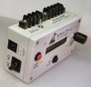 Electronic Counter and Quadrature Encoder Reader
The counter can read one or two digital or analog sensors and display the running total on an organic LED display.
The counter controls the speed of an attached DC motor and can stop it when a certain count is reached.
The project features a continuous rotation rotary encoder dial, with a cut-away view and an explanation of how quadrature encoding works.
Finally, there is an in-depth example of why interrupts are better than polling.
 Maximum Sampling in Software
When sampling at the maximum software rate, the signal itself may affect the software, resulting in inaccurate readings.
Here is an example of how I debugged an issue and doubled the rate.
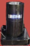
 Optical Encoder with Digital Quadrature Output
Quadrature encoders use a pair of photosensors to detect the rotations of an optical target disc.
A digital output produces a clean square wave that a robot microcontroller can use to determine motor speed and motor rotational direction.
This particular encoder uses red LEDs rather than infrared to make it easier to aim and debug.
The article includes oscilloscope traces and the circuit laid out on a solderless breadboard.
 Mini-Mill Digital Tachometer
Hobbyists have to experiment with speeds and feeds to get optimum cutting rates and surface smoothness without tool breakage.
An RPM display is necessary to take advantage of existing tool rotation rate charts, but the MicroLux milling machine doesn’t have such a readout.
Here’s how I made mine with almost no modification to the existing mill. Yes, it’s yet another tach project.
 Combination Handheld Tachometer, Thermometer, and Counter
Inspired by the need to measure dc motor speed and detect overheating, this 68HC908KX8 microcontroller-based circuit displays various statistics on six-digit, eight-segment, numeric LEDs.
See movies of a thermistor in action as well as a reflective or interrupt-based photosensor counting.
 Second-Generation Combination Tachometer
To display RPMs on 4-inch tall LEDs, the original digital tachometer circuit needed to be redesigned.
A comparator was successfully included along with a canned oscillator, quad-tach mode, and adjustable overheat temperature setting.
 Debounced Counter
A break-before-make double-throw switch is debounced by a NAND SR latch. The signal is fed into a decade counter and a LED decoder driver.
If you don’t know what that means (and you’d rather not use a microcontroller) then read this article.

