

(article continued from previous page)
We’re making a coupler to attach a LEGO wheel to a standard gearmotor. At this point, a metal rod has been selected, cut, put into a lathe, faced, and chamfered.
If you’re machining aluminum, use a cutting oil or kerosene to keep the drills and cutting tools lubricated. Lubricant is unnecessary for machining brass.
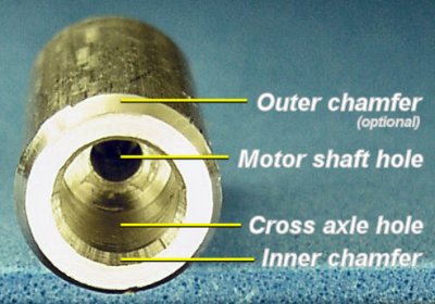
A preview of the machining needed to create a cross axle Lego coupler.
Before we start drilling, here is what we’re trying to achieve:

A large rigid drill starts a centered hole on a rod in a lathe.
To avoid eccentricity (wobbling), it is important that the holes for the axle and motor shaft line up with each other. A reliable way to begin drilling a hole is to start with a sturdy spotting drill or center drill. The drill is a much larger diameter than needed to drill the actual hole. We’re taking advantage of its greater rigidity to avoid the flexing that would occur with a smaller diameter drill.
The center drill is placed in a drill chuck on the tailstock of the lathe. The tailstock is built to be centered with the lathe spindle that holds the metal rod. On a lathe, the rod rotates, not the drill. These factors combine to provide a beautifully centered starting hole.
This is much, much easier than trying to center a rod on a milling machine!

On a lathe, drilling the smaller hole for the motor shaft and the larger hole for the Lego cross axle.
Replace the center drill with a smaller diameter drill that matches the diameter of the gearhead motor shaft. For the Solarbotics GM7 2.17 mm shaft, I drilled the center of the coupler with a #44 drill (0.0860 inches or 2.1844 mm).
It is slightly more difficult to determine the correct drill size for the plastic Lego cross axle. If you make your coupler out of plastic, then a #12 drill seems to work well, as the plastic coupler will stretch during drilling and then rebound to a slightly smaller diameter when the drill is removed. If you make your coupler out of metal and you plan to use epoxy to hold the cross axle in the coupler, then a #13 is a good fit. However, if you make your coupler out of metal and you plan to force fit the cross axle into the coupler, then select a #14 drill. (In other words, some experimentation may be necessary.)
On a mill, I normally drill the smaller diameter hole (for the motor shaft) all of the way through the coupler and then use it as a pilot hole for the larger hole (for the cross axle). However, on a lathe, I think the arrangement of the lathe itself should center the drill as long as the holes are started cleanly.
So, on a lathe, it may be best to start with the larger drill and then use the smaller drill. This means you can use a shorter (less bendy) drill for the small drill. And, because a lot of material has been removed by the larger drill, the smaller drill is less likely to clog.
Or, another option is to drill the large hole, cut off the rod, flip it around in the lathe, and then drill the small hole. But, removing the rod from the lathe chuck introduces small angular errors. Normally, a machinist tries to complete as many lathe operations as possible without removing the workpiece.
After some testing, I finally decided to use a center drill, then the larger drill (cross axle), and finally the smaller drill (motor shaft) -- without ever removing the rod from the lathe.
Checking the depth of the Lego cross axle hole.
The tailstock on the Microlux lathe has a scale to approximately indicate the depth of a drilled hole. When drilling the hole for the cross axle, I drill for four or five notches on the scale, but then I pull out and test the depth with a Lego piece or an appropriate-length screw. A depth of about 7.5 mm to 8 mm is sufficient to hold the axle.
After drilling the cross axle hole, I recommend briefly switching back to the large center drill to gently chamfer (slightly drill) the inside edges at the end of the hole. This will help guide the axle into position and will prevent the axle sides from being scrapped or the epoxy from being wiped off as the axle is inserted. (An example without the chamfer is shown on the next page.)
The Solarbotics GM7 gearmotor’s shaft length is about 9 mm. Accounting for the 8 mm cross axle hole and 1 mm of slop in between, this coupler should be about 18 mm long.

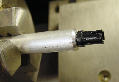
Cutting off a length of rod on a lathe using a cut-off blade and a dead center in the tailstock.
Cutting off a metal rod in a lathe is accomplished with a cutoff tool that has a blade. During cut-off, the speed of the lathe is reduced to 1/3 or 1/4 of the speed normally used for other lathe operations.
The cutoff blade is sharp only at the tip, not the sides. As the blade progresses into the workpiece, the cut portions of the rod spring back slightly, causing significant friction. Additionally, the rod may flex or bend, further pressing against the sides of the cut-off blade.
Inserting and withdrawing the blade can help remove excess material from the sides of the rod during cutting. Additionally, bending can be reduced by supporting the end of the rod with a live center or lubricated dead center in the tailstock. (For the coupler, it is possible to cut off such a narrow diameter and short length without tailstock support.)
If you don’t have a cut-off tool, you can simply remove the rod and cut it off with a hacksaw. Then, insert the coupler into the lathe and smooth the rough end as described on the previous page.
The final steps are to drill setscrew holes and install the cross axle...